Exhaust gas purification system

a technology of exhaust gas purification system and exhaust gas, which is applied in the direction of exhaust treatment electric control, electrical control, separation process, etc., can solve the problems of exhaust gas purification efficiency reduction, cylinder scorching, and dpf obstruction, and achieve the effect of suppressing the decline in gas mileag

Active Publication Date: 2015-03-10
ISUZU MOTORS LTD
View PDF15 Cites 8 Cited by
  • Summary
  • Abstract
  • Description
  • Claims
  • Application Information

AI Technical Summary

Benefits of technology

[0017]In consideration thereof, an object of the present invention is to provide an an exhaust gas purification system which is capable of appropriately aborting DPF regeneration to suppress a decline in gas mileage in a vehicle condition where temperature rise control of exhaust gas becomes unstable when the DPF regeneration is performed using exhaust pipe injection.
[0019]With the exhaust gas purification system according to the present invention, when DPF regeneration is performed using exhaust pipe injection, the DPF regeneration can be appropriately aborted to suppress a decline in gas mileage in a vehicle condition where temperature rise control of the exhaust gas becomes unstable.

Problems solved by technology

PM collected from the exhaust gas and accumulated in the DPF causes clogging of the DPF and reduces exhaust gas purification efficiency.
While post-injection enables a conventional diesel engine and a conventional exhaust gas purification system to be utilized as-is, since the unburnt fuel is directly injected into a cylinder, a problem of oil dilution occurs in that engine oil is contaminated and diluted by a fuel component and an ensuing decline in a lubricating function causes scorching of a cylinder and the like.

Method used


Image

  • Exhaust gas purification system
  • Exhaust gas purification system
  • Exhaust gas purification system

Examples


Embodiment Construction

[0022]Hereinafter, preferred embodiments of the present invention will be described with reference to the accompanying drawings.

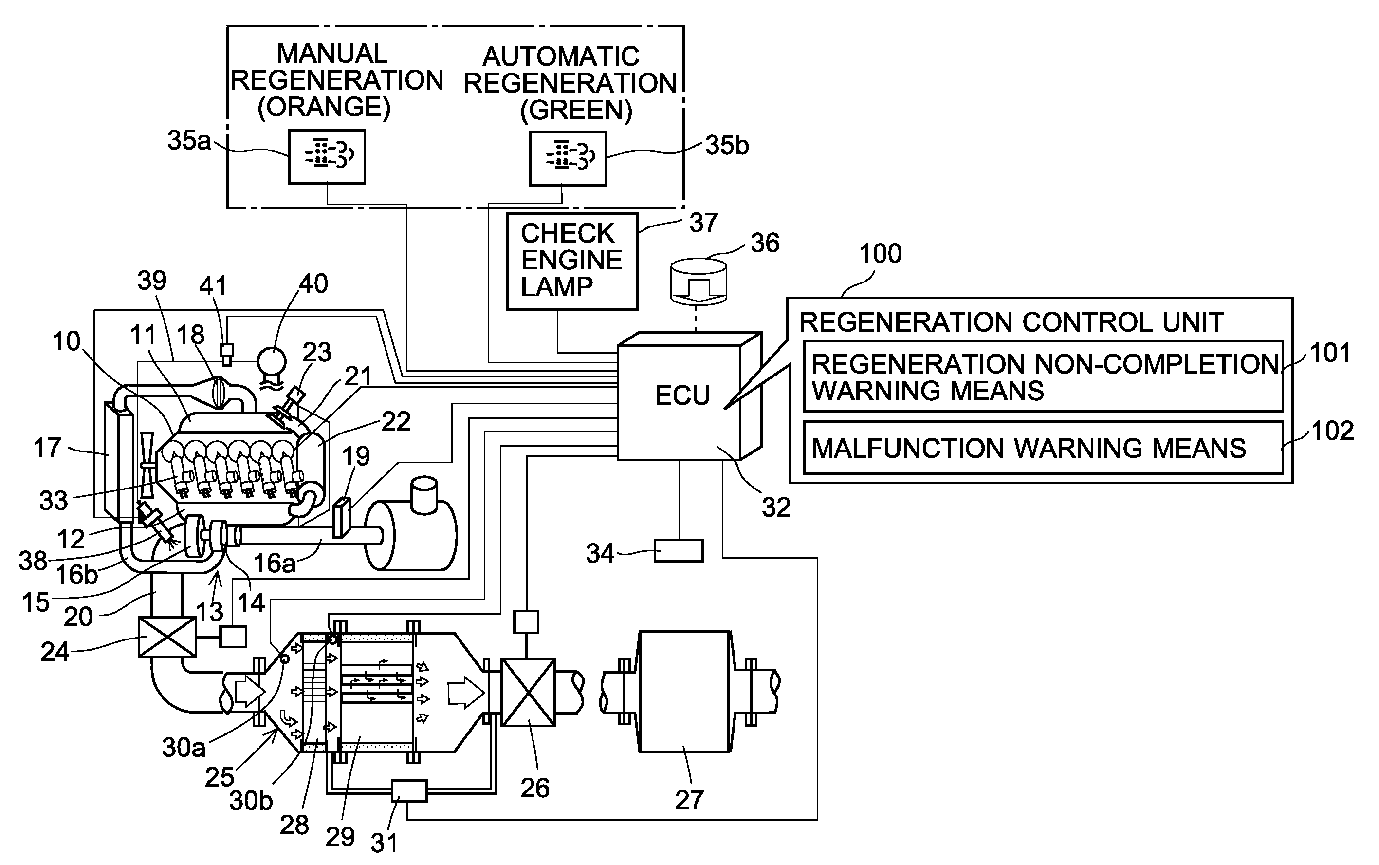
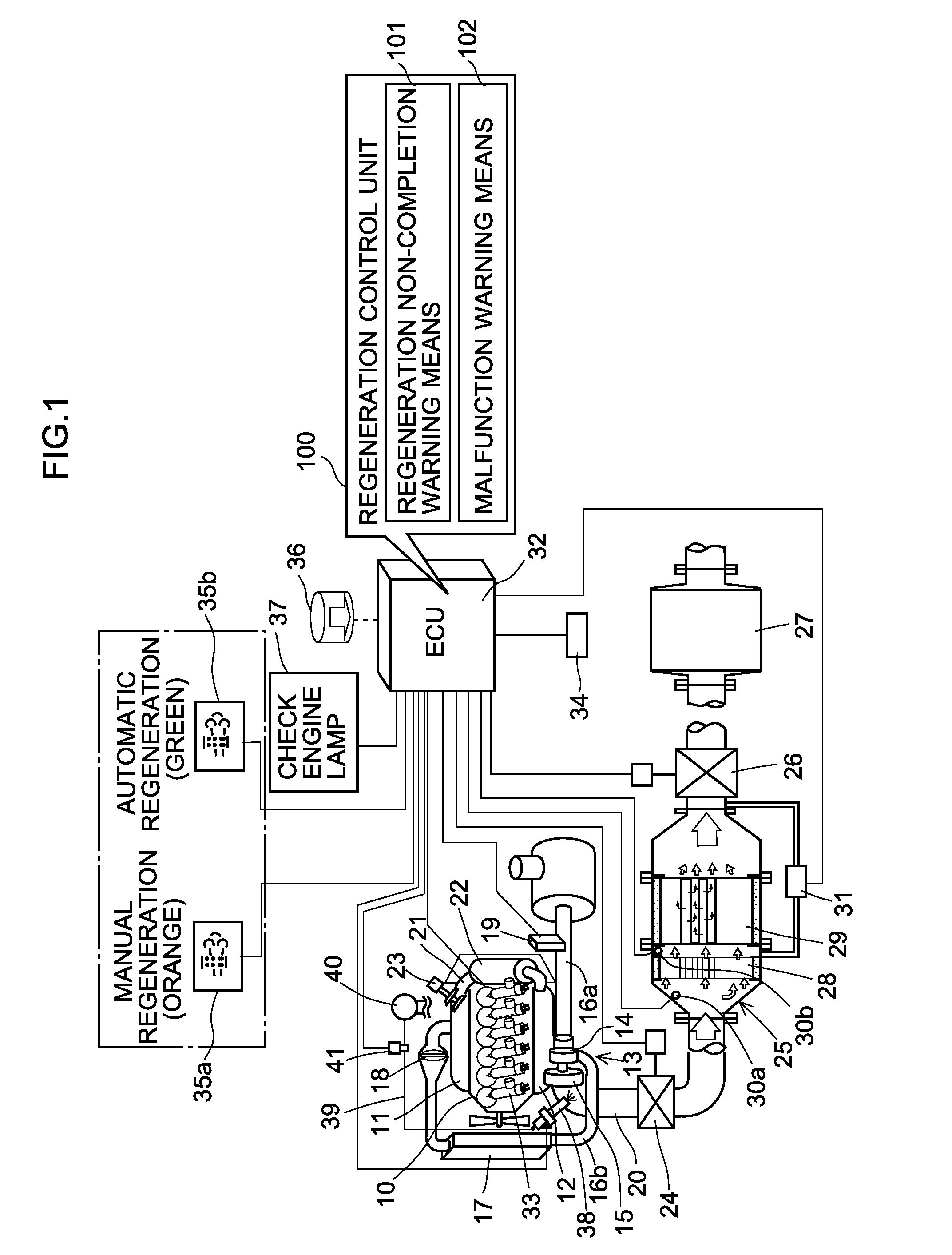
[0023]FIG. 1 is a system diagram showing an exhaust gas purification system according to the present embodiment.

[0024]In FIG. 1, an intake manifold 11 and an exhaust manifold 12 of a diesel engine 10 are respectively coupled to a compressor 14 and a turbine 15 of a supercharger (turbocharger) 13. Pressure of air from an upstream intake pipe 16a is raised by the compressor 14, and the air is cooled when passing through an intercooler 17 of a downstream intake pipe 16b and supplied from the intake manifold 11 to the diesel engine 10 via an intake throttle (intake throttle valve) 18. Exhaust gas from the diesel engine 10 drives the turbine 15 and is subsequently discharged to an exhaust pipe 20.

[0025]The upstream intake pipe 16a is provided with an MAF (Mass Air Flow) sensor 19 which measures an intake volume. The MAF sensor 19 controls a degree of opening of ...


PUM

PropertyMeasurementUnit
temperatureaaaaaaaaaa

Abstract

An exhaust gas purification system includes a diesel particulate filter (“DPF”) which collects particulate matter (“PM”) in exhaust gas, an exhaust pipe injector which performs exhaust pipe injection, and a DPF regeneration control unit which performs temperature rise control of an exhaust gas temperature by the exhaust pipe injection to regenerate the DPF when the PM collected by the DPF exceeds a fixed amount and which, during the regeneration, integrates an amount of time during which the exhaust gas temperature exceeds a PM combustion temperature and completes the regeneration when an integrated value thereof reaches a set regeneration completion value. The DPF regeneration control unit aborts the regeneration when, during regeneration, a total amount of the exhaust pipe injection exceeds an upper limit before the integrated value.

Description

CROSS-REFERENCE TO RELATED APPLICATIONS[0001]This application claims the foreign priority benefit of Japanese Application No. 2010-134511 filed Jun. 11, 2010, the contents of which are incorporated herein by reference, which serves as priority for PCT Application No. JP2011 / 063320 filed Jun. 10, 2011.TECHNICAL FIELD[0002]The present invention relates to an exhaust gas purification system that collects PM (Particulate Matter) in exhaust gas from a diesel engine.BACKGROUND ART[0003]Exhaust gas purification systems have been developed which collect PM in exhaust gas from a diesel engine using a DPF (Diesel Particulate Filter) such as a DPD (Diesel Particulate Defuser) that is a type of DPF to reduce an amount of PM that is discharged to the outside (for example, refer to Patent Document 1).[0004]Examples of such an exhaust gas purification system include a continuous regeneration DPF system in which a DOC (Diesel Oxidation Catalyst) is provided upstream of a DPF.[0005]PM collected from...

Claims


Application Information

Patent Timeline
Patent Type & Authority Patents(United States)
IPC IPC(8): B01D50/00B01D39/20B01D39/14B01D39/06B01D24/00B01D46/00F01N3/025F01N9/00F01N11/00F02D41/02
CPCB01D46/0063F01N3/0253F01N9/002F01N11/002F02D41/029Y02T10/47F01N2550/04F02D2200/0625F02D2200/0812F02D2200/604F01N2610/03F01N2900/1404F01N2900/1606F01N2900/0418Y02T10/40B01D46/84
Inventor HASEYAMA, TAKASHIGOTOU, SHINJIOOHIRA, HIROYUKI
Owner ISUZU MOTORS LTD
Why Eureka
Try Eureka