Integrated electronic system mounted on aircraft

an electronic system and integrated technology, applied in the direction of data switching network, electrical apparatus casing/cabinet/drawer, instruments, etc., can solve the problems of increasing preventing the saving of the weight of the fuselage, and the increase of the number of auxiliary components of electronic devices, so as to reduce electronic devices and wires. , the effect of improving fault toleran

Active Publication Date: 2015-03-10
KAWASAKI HEAVY IND LTD
View PDF18 Cites 2 Cited by
  • Summary
  • Abstract
  • Description
  • Claims
  • Application Information

AI Technical Summary

Benefits of technology

[0018]As described above, in the case of the small-sized aircraft, the amount of the wires cannot be reduced sufficiently when the IMA units are merely used (see FIG. 8B). Even if an attempt is made to apply to the utility systems in the small-sized aircraft, the configuration used in the large-sized aircraft, i.e., configuration using the RDCs and the data buses, a high advantage cannot be achieved. This is because, the configuration used in the large-sized aircraft, in which the wires laid out in the respective parts of the fuselage are replaced with the RDCs and the data buses, can reduce the amount of the wires more effectively in a greater fuselage, but cannot reduce it effectively in a smaller fuselage.
[0025]In accordance with the configuration, the identical transmission protocol is preferably set for the integrated data bus which is an external bus of an IMA unit and an in-casing data bus which is an internal bus of the IMA unit. Therefore, by connecting the bus switch module to the integrated data bus, a single network can be constructed in the overall system irrespective of inside or outside of the IMA unit. Therefore, as compared to a case where a transmission protocol is different between the external bus and the internal bus and data transfer processing between them is performed by a CPU module, if a CPU module in a particular IMA unit fails, a CPU module in another IMA unit can easily access input / output signals of the particular IMA unit, and can easily perform the function of the CPU module in a failure condition. Thus, fault tolerance can be improved. In addition, this has an advantage that a processing ability of the CPU module is not used in the data transfer processing. That is, in accordance with the present invention, a technique can be provided and implemented in which in the electronic system mounted on the aircraft comprising a plurality of electronic devices including IMA units, the system is not affected significantly by occurrence of a failure in the CPU module in a particular electronic device, and fault tolerance can be improved.
[0027]In accordance with this configuration, rather than RDCs, the MIA units are provided in the nose part, the center part, and the aft part of the fuselage which are parts where control systems are crammed and are connected together via the integrated data bus. This can minimize the IMA units in number, and a greater part of wires can be replaced by the integrated data bus. Therefore, even in utility systems mounted in a small-sized aircraft, the electronic devices and the wires can be lessened significantly.
[0028]In the integrated electronic system mounted on the aircraft, as configured above, the integrated modular avionics units may be configured such that two or more integrated modular avionics units are provided in each of the nose part, the center part, and the aft part of the fuselage. This makes it possible to construct at least a double redundant system in each of the parts and improve reliability of the system.
[0031]In accordance with this configuration, since the signal conversion module standardizes input / output signals in different formats, and then the signals are processed, existing components using different signal formats may be used as terminal devices. Therefore, in the utility systems of the small-sized aircraft, integration using the existing components can be implemented. Since the signal conversion module is constituted by the analog circuit, there is no need for programs implemented for digital data processing, and therefore development cost can be reduced.
[0036]As should be appreciated from the above, in accordance with the present invention, it is possible to implement an electronic system mounted on an aircraft which can more effectively reduce electronic devices and wires by integration of control systems, use existing components as terminal devices in control systems, and improve fault tolerance.

Problems solved by technology

With an increase in the electronic devices and the wires, the weight of the fuselage increases, which precludes the fuselage weight saving.
With an increase in the kinds of the electronic devices, simplification of the configuration is precluded, and auxiliary components of the electronic devices increase in number, which increases cost.
Furthermore, with an increase in the electronic devices and the wires, a space occupied by these electronic devices and the wires increases, but a passenger space and a cargo space are narrowed, which will result in a reduced transportation efficiency.
However, it is difficult to construct a common system of the utility systems because components in the utility systems are unique to the fuselage.

Method used


Image

  • Integrated electronic system mounted on aircraft
  • Integrated electronic system mounted on aircraft
  • Integrated electronic system mounted on aircraft

Examples


Embodiment Construction

[0073]Hereinafter, preferred embodiments of the present invention will be described with reference to the drawings. Throughout the drawings, the same or corresponding components are identified by the same reference symbols and will not be described in repetition.

[0074][Configuration of Integrated Electronic System Mounted on Aircraft]

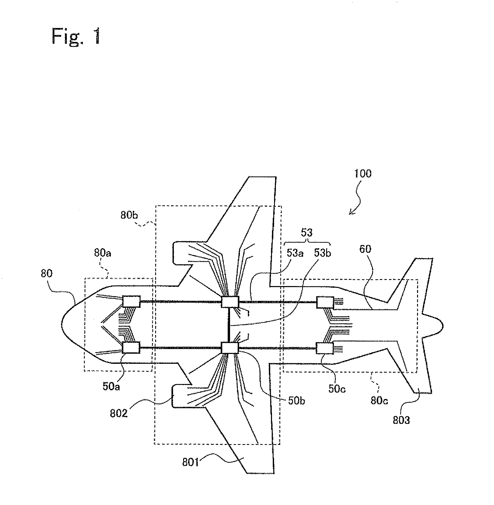
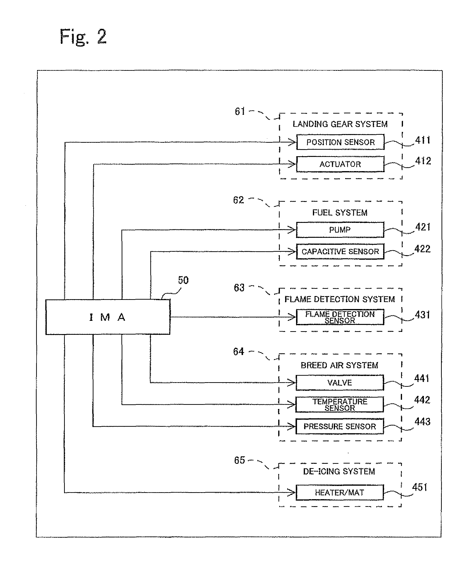
[0075]First of all, an overall configuration of an integrated electronic system mounted on an aircraft of the present embodiment will be specifically described with reference to FIGS. 1 and 2. In the present embodiment, for easier explanation, the “integrated electronic system mounted on the aircraft” will be referred to as “integrated electronic system.”

[0076]FIG. 1 is a schematic wiring diagram showing exemplary layout of integrated modular avionics (IMA) units and wires in the integrated electronic system according to the embodiment. FIG. 2 is a block diagram showing a schematic configuration of the integrated electronic system of FIG. 1.

[0077]As sho...


PUM


Abstract

The present invention provides an electronic system mounted on an aircraft which can effectively reduce electronic devices and wires by integration of control systems. Specifically, a fuselage (80) of an aircraft (100) is divided into a nose part (80a), a center part (80b), and an aft part (80c), and two IMAs (integrated modular avionics units) (50a to 50c) are provided in each of these parts. The IMA units (50a to 50c) are interconnected via an integrated data bus (53) to construct an integrated electronic system mounted on the aircraft. The system is suitably used for integrating utility systems except for avionics systems, among a plurality of control systems mounted on the aircraft, and is also applicable to integration of the avionics systems.

Description

TECHNICAL FIELD[0001]The present invention relates to an electronic system mounted on an aircraft and including a plurality of electronic devices to implement functions of the aircraft. Specifically, the present invention relates to an integrated electronic system mounted on an aircraft in which a plurality of functions of the aircraft are integrated.BACKGROUND ART[0002]Various electronic devices (avionics devices) exclusively for aircraft are incorporated into the aircraft to implement functions of gauge display, communication, navigation, flight management, etc., of the aircraft. The avionics devices are provided in respective parts of a fuselage. The avionics devices are connected to various terminal devices associated with gauge display, communication, navigation, flight management, etc., and are interconnected to construct one system (hereinafter referred to as “electronic system mounted on an aircraft”). The avionics devices are configured as LRUs (line replaceable units) so t...

Claims


Application Information

Patent Timeline
Patent Type & Authority Patents(United States)
IPC IPC(8): G06F13/00B64D47/00H04L12/40
CPCB64D47/00H04L12/40006H04L2012/4028B64D43/00B64D2221/00
Inventor MITANI, YOICHITAMARU, MASAHIROIKARASHI, REIICHIISOBE, TAISEI
Owner KAWASAKI HEAVY IND LTD
Why Eureka
Try Eureka