
Gyro sensor, electronic apparatus, and method of manufacturing gyro sensor

Active Publication Date: 2015-03-17
SEIKO EPSON CORP
View PDF2 Cites 1 Cited by
  • Summary
  • Abstract
  • Description
  • Claims
  • Application Information

AI Technical Summary

Benefits of technology

The patent text describes a way to make a gyro sensor that can maintain its optimal performance even when subjected to frequent changes in structure. By adjusting the ratio of the widths of the detecting and driving springs, the sensor can detect accurately over a wide range of frequencies. The text also describes a method for making the sensor that allows for uniform etching during manufacturing. These technical effects make the gyro sensor more reliable and efficient for use in various applications.

Problems solved by technology

However, in the case of the adjustment method that uses laser light, there is a limit on a range of frequencies that can be adjusted by a laser apparatus.
Thus, it may be difficult to adjust the frequencies if a frequency fluctuation is greater than the limit.
As a result, it is difficult to obtain a desired detuning frequency, and the sensitivity properties and the detection band properties of the gyro sensor may deteriorate.
However, if the electrostatic force is increased too much, a sticking phenomenon of the structural body may occur.
Thus, a resonant frequency adjustment method that uses electrostatic force may cause the risk of sticking, and there is a problem in that it is difficult to adjust the frequency dramatically.

Method used


Image

  • Gyro sensor, electronic apparatus, and method of manufacturing gyro sensor
  • Gyro sensor, electronic apparatus, and method of manufacturing gyro sensor
  • Gyro sensor, electronic apparatus, and method of manufacturing gyro sensor

Examples


experimental example

2. Experimental Example

[0111]Next, an experimental example will be described. The invention is not limited to the following experiment.

[0112]A structural body S was used in this experimental example. FIG. 7 is a plan view schematically illustrating the structural body S. In the following description, members of the structural body S used in this experimental example having the same functions as the constituent members of the gyro sensor 100 according to the present embodiment will be denoted by the same reference numerals, and detailed description thereof will be not provided.

[0113]As illustrated in FIG. 7, the structural body S has the same configuration as the gyro sensor 100 except that the detecting portion 120 and the detecting fixed electrode 140 are not provided, and the driving support portion 112 does not have the opening 113. That is, the structural body S includes the vibrating structural body 104, the driving fixed electrode 130, and the fixing portion 150. The vibrating...


PUM

PropertyMeasurementUnit
Frequencyaaaaaaaaaa

Abstract

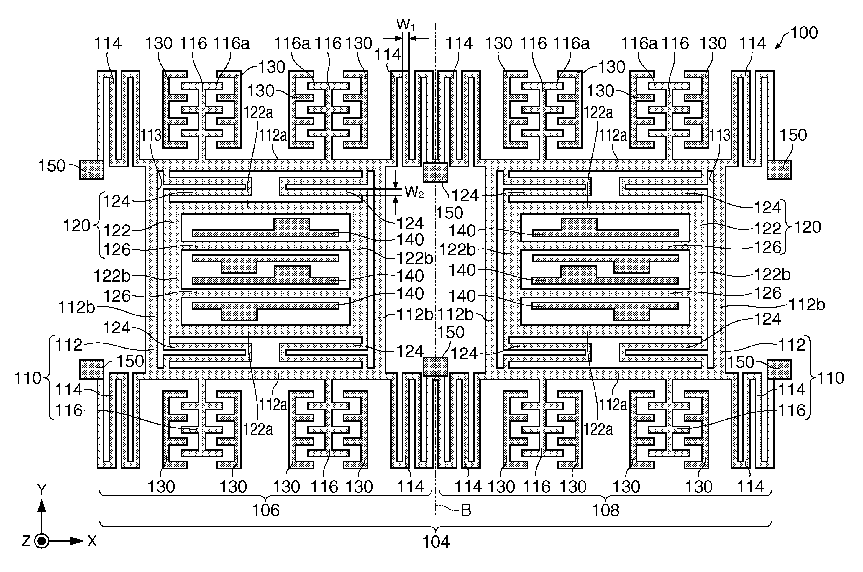
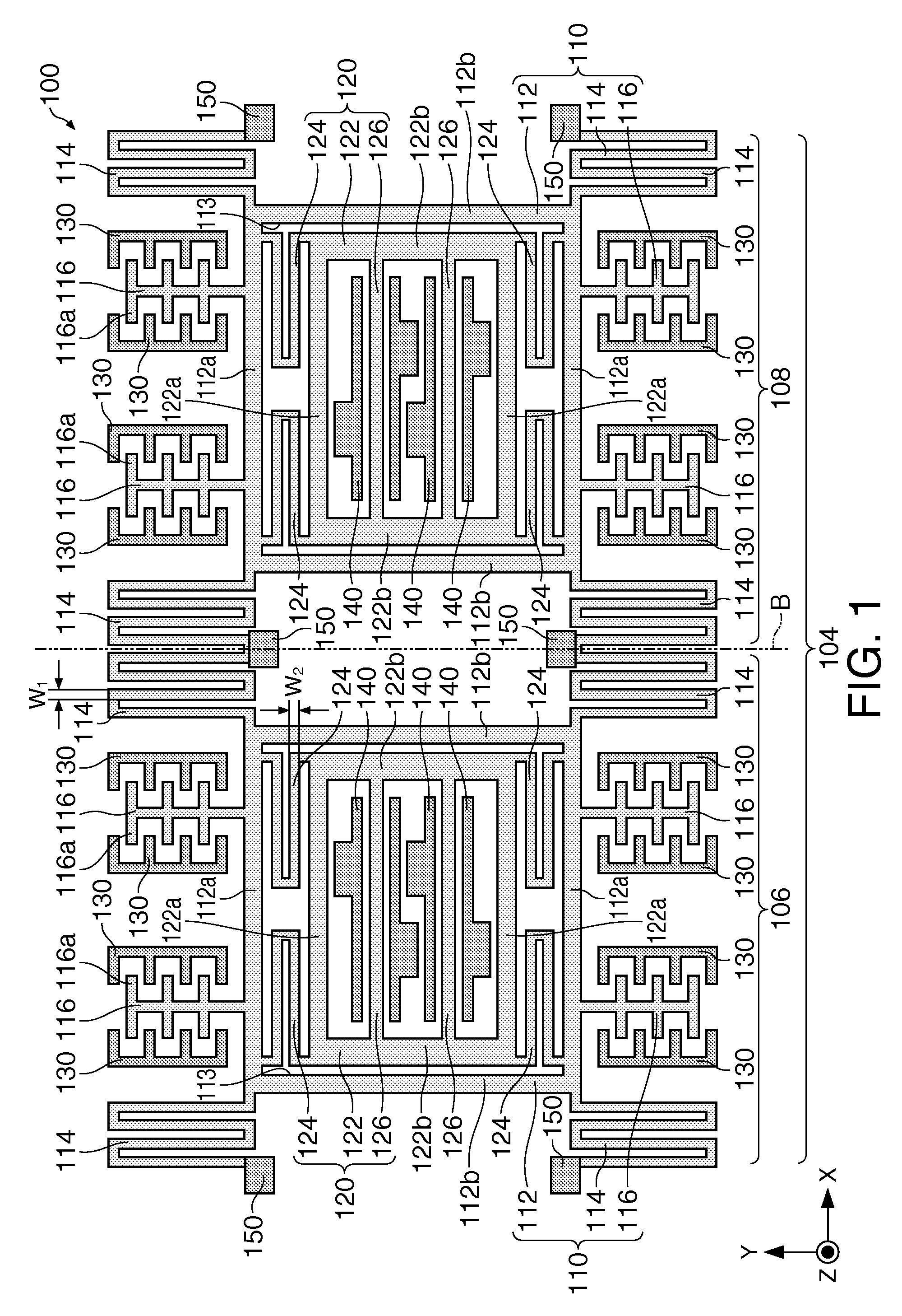
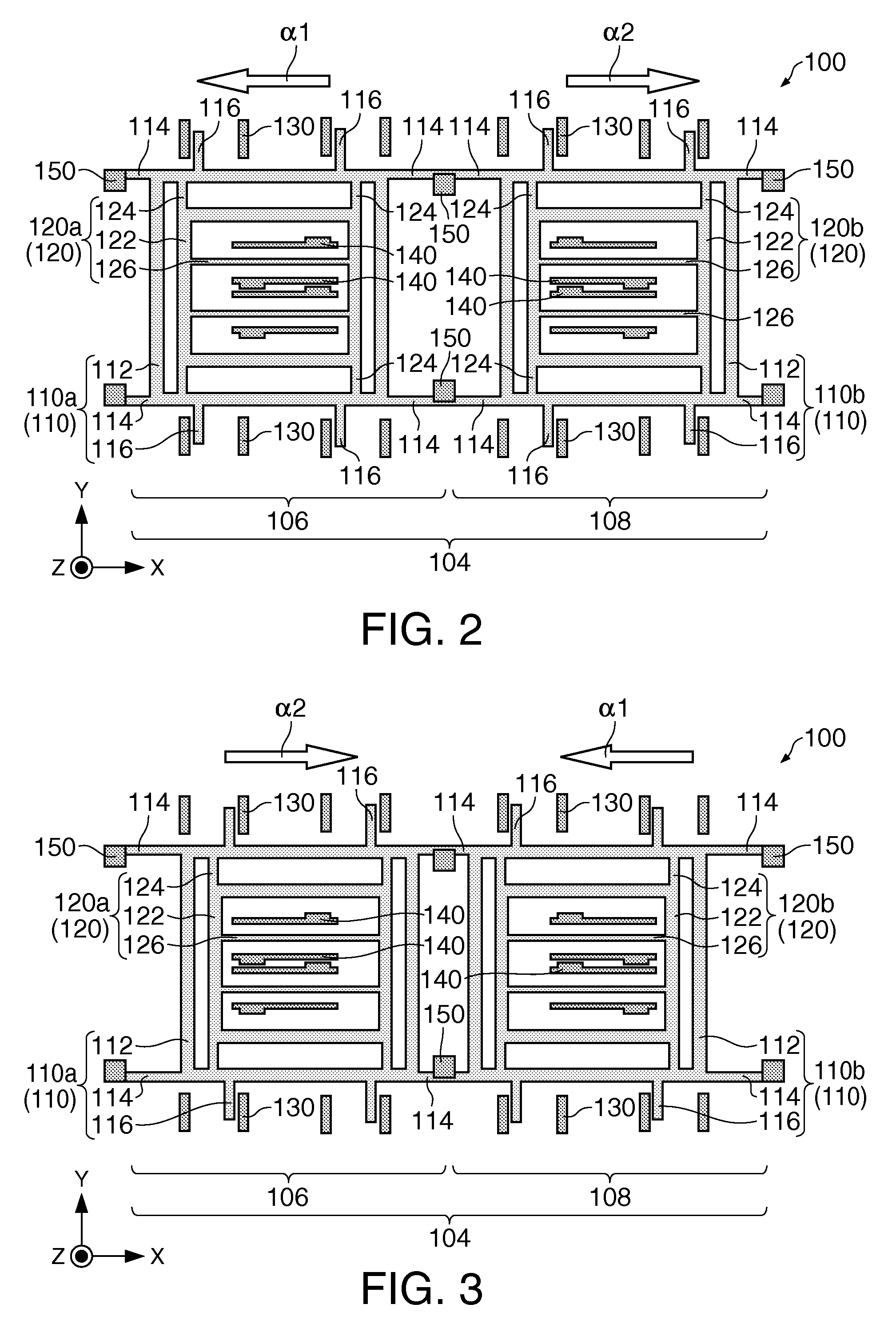
A gyro sensor according to the invention includes a driving portion that includes a driving support portion connected to a driving spring portion and a detecting portion that includes a detecting support portion connected to the driving support portion with the detecting spring portion interposed. The driving support portion is configured to vibrate in a first axis (X-axis) direction, and the detecting support portion is configured to be displaced in a second axis (Y-axis) direction orthogonal to the first axis (x-axis). When the resonant frequency of the driving portion is f1, the resonant frequency of the detecting portion is f2, the width of the driving spring portion is w1, and the width of the detecting spring portion is w2, Expression (1) below is satisfied.0.87(f2 / f1)≦(w2 / w1)≦1.13(f2 / f1)  (1)(where, w1≠w2 and f1≠f2).

Description

BACKGROUND[0001]1. Technical Field[0002]The invention relates to a gyro sensor, an electronic apparatus, and a method of manufacturing a gyro sensor.[0003]2. Related Art[0004]In recent years, inertial sensors that detect a physical quantity using a silicon microelectromechanical system (MEMS) technique have been developed. Among these inertial sensors, a gyro sensor (angular velocity sensor) that detects angular velocity is used for a hand-shake correction function of digital still cameras (DSC), a motion sensing technique of game machines, and the like.[0005]The gyro sensor includes a driving portion that is actively vibrated and a detecting portion that is displaced by a Coriolis force when an angular velocity is applied. Thus, it is possible to detect an angular velocity from the displacement amount of the detecting portion. In such a gyro sensor, since a difference (detuning frequency) between the resonant frequency of the driving portion and the resonant frequency of the detect...

Claims


Application Information

Patent Timeline
IPC IPC(8): G01C19/56G01C19/5747
CPCG01C19/5747
Inventor TAKIZAWA, TERUO
Owner SEIKO EPSON CORP
Learn More