Ultrasonic atomization method and apparatus

a technology of ultrasonic atomization and liquid, applied in the direction of chemistry apparatus and processes, evaporation by spraying, separation processes, etc., can solve the problems of difficult to increase the efficiency of atomization, and achieve the effect of efficient separation

Inactive Publication Date: 2015-03-17
HONKE MATSUURA BREWERY
View PDF12 Cites 1 Cited by
  • Summary
  • Abstract
  • Description
  • Claims
  • Application Information

AI Technical Summary

Benefits of technology

[0010]The apparatus shown in FIG. 2 is designed to ultrasonically oscillate and atomize a liquid into mists. In this apparatus, a liquid column P generated in projecting upwardly of the liquid surface W by means of the ultrasonic oscillation is blasted by a laterally blown wind, by which wind the liquid column P is bent down in a parallel direction with respect to the liquid surface W and thus the atomization efficiency is improved. By bending down the liquid column in a parallel direction with respect to the liquid surface, the apparatus can efficiently atomize the liquid inside the liquid column because attenuation of the vertical ultrasonic oscillation caused by collision is effectively prevented. However, if an even higher atomization efficiency is available than this particular atomization apparatus, it will be possible to further reduce running and equipment costs to minimum. In particular, the apparatus shown in FIG. 2 suffers a disadvantage that it is difficult to increase an atomization efficiency by using multiple ultrasonic oscillators in order to increase an amount of atomization per unit time.
[0011]The present invention has been made to further improve the efficiency of atomization, and the object of the invention is to provide an ultrasonic atomization method and apparatus providing such a highly efficient ultrasonic atomization method and apparatus as may exceed a conventional method and apparatus of atomization.

Problems solved by technology

In particular, the apparatus shown in FIG. 2 suffers a disadvantage that it is difficult to increase an atomization efficiency by using multiple ultrasonic oscillators in order to increase an amount of atomization per unit time.

Method used


Image

  • Ultrasonic atomization method and apparatus
  • Ultrasonic atomization method and apparatus
  • Ultrasonic atomization method and apparatus

Examples


Embodiment Construction

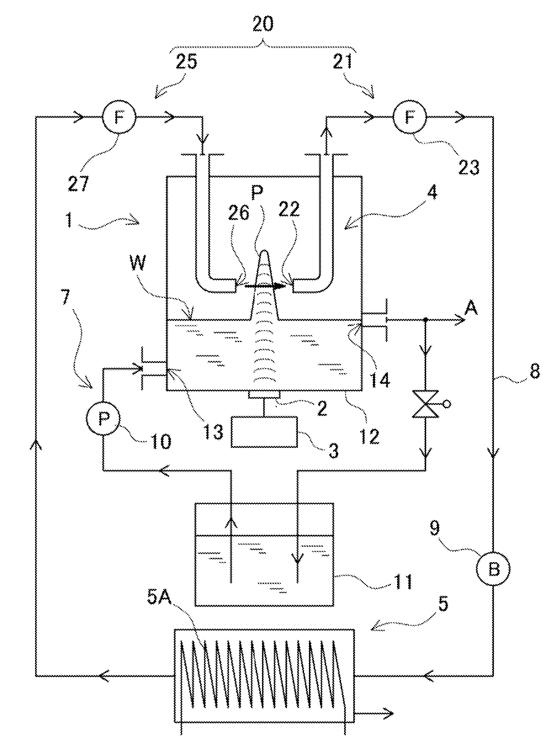
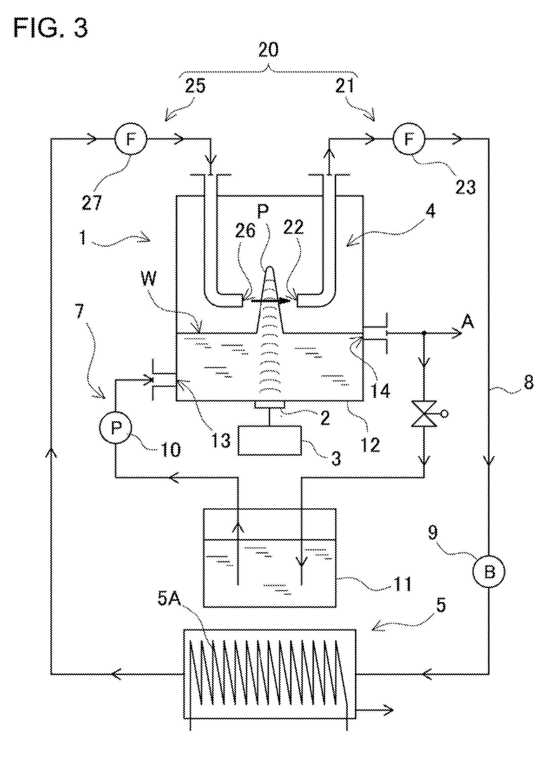
[0052]Embodiments of the present invention will now be discussed in conjunction with the accompanying drawings. It should be noted here that the following embodiments are intended to be illustrative of an ultrasonic atomization method and apparatus to embody the technical ideas of the invention, and the inventive method and apparatus are, in no way, limited to the ultrasonic atomization method and apparatus described below.

[0053]Further, in the present disclosure, reference numerals corresponding to members shown in the embodiments are suffixed to members shown in the “CLAIMS” and “MEANS TO SOLVE THE PROBLEM” in order to facilitate appreciation of the claims. However, the members shown in the claims shall, in no way, be specified to those members shown in the embodiments.

[0054]In the present ultrasonic atomization method and apparatus, the liquid is ultrasonically oscillated to atomize the mists into the carrier gas. A specific example in which the ultrasonic atomization apparatus i...


PUM


Abstract

In the ultrasonic atomization method, a liquid is ultrasonically oscillated in an atomization chamber 4 and a liquid column P is projected in carrier gas to thus atomize the liquid into mists, the carrier gas carrying the atomized mists outwardly of the atomization chamber 4; the carrier gas is forcibly sucked from a lateral point being away at a distance (d1) of 5 cm or less from a center axis m of the liquid column P and thereby a gas flow is blown across the liquid column P; the mists are separated away from the liquid column P by means of the blown gas flow; and such separated mists are transferred outwardly of the atomization chamber 4 by means of the carrier gas.

Description

BACKGROUND OF THE INVENTION[0001]1. Technical Field[0002]The present invention relates to a method and apparatus for atomizing a liquid into fine mists. The invention relates in particular to an ultrasonic atomization method and apparatus that is used as an apparatus for atomizing Sake, alcohol used for Sake production, petroleum, crude oil or the like into the mists to obtain a highly concentrated solution as a target substance, or which is optimally used as a humidifier, etc. for atomizing water into the mists to be vaporized into the air.[0003]2. Background Art[0004]The present inventor has previously developed an apparatus for atomizing a liquid containing alcohol into mists, collecting such atomized mists, and separating highly concentrated alcohol (see Patent Document 1). This separation apparatus can, for example, ultrasonically oscillate a starting liquid containing alcohol, atomize the liquid into fine mists to be sent into carrier gas, separate and collect the atomized mis...

Claims


Application Information

Patent Timeline
Patent Type & Authority Patents(United States)
IPC IPC(8): B05B1/08B01D1/14B01D1/20B05B17/06
CPCB05B17/0615B01D1/20B01D1/14
Inventor MATSUURA, KAZUO
Owner HONKE MATSUURA BREWERY
Why Eureka
Try Eureka