Turbine bucket angel wing features for forward cavity flow control and related method

a technology of forward cavity and flow control, applied in the field of rotary machines, can solve the problems of damage to components, loss of efficiency and thus output, and disadvantageous leakage of hot gas into the wheelspace by this pathway

Active Publication Date: 2015-03-17
GENERAL ELECTRIC CO
View PDF11 Cites 16 Cited by
  • Summary
  • Abstract
  • Description
  • Claims
  • Application Information

AI Technical Summary

Benefits of technology

[0014]In still another aspect, method of controlling secondary flow at a radial gap between a rotating turbine disk mounting a plurality of buckets and an adjacent nozzle, the method comprising: locating at least one angel wing seal on a leading edge of each of the plurality of buckets extending axially toward the nozzle to thereby form a barrier between a hot stream of combustion gases on a radially outer side of the angel wing seal and purge air in a wheel space radially inward of the at least one angel wing seal; and providing plural openings in the angel wing seal enabling purge air to flow into an area radially outward of the angel wing seal to thereby prevent the combustion gases from impinging on the angel wing seal flange.

Problems solved by technology

As alluded to above, the leakage of the hot gas into the wheelspace by this pathway is disadvantageous for a number of reasons.
First, the loss of hot gas from the working gas stream causes a resultant loss in efficiency and thus output.
Second, ingestion of the hot gas into turbine wheelspaces and other cavities can damage components which are not designed for extended exposure to such temperatures.
While cooling air from the secondary flow circuit is very beneficial for the reasons discussed above, there are drawbacks associated with its use as well.
For example, the extraction of air from the compressor for high pressure cooling and cavity purge air consumes work from the turbine, and can be quite costly in terms of engine performance.
Moreover, in some engine configurations, the compressor system may fail to provide purge air at a sufficient pressure during at least some engine power settings.
Thus, hot gases may still be ingested into the wheelspace cavities.
For example, it has been determined that even if the angel wing seal is effective and preventing the ingress of hot combustion gases into the wheelspaces, the impingement of combustion gas flow vortices on the surface of the seal may damage the seal and shorten the service life of the bucket.

Method used


Image

  • Turbine bucket angel wing features for forward cavity flow control and related method
  • Turbine bucket angel wing features for forward cavity flow control and related method
  • Turbine bucket angel wing features for forward cavity flow control and related method

Examples


Embodiment Construction

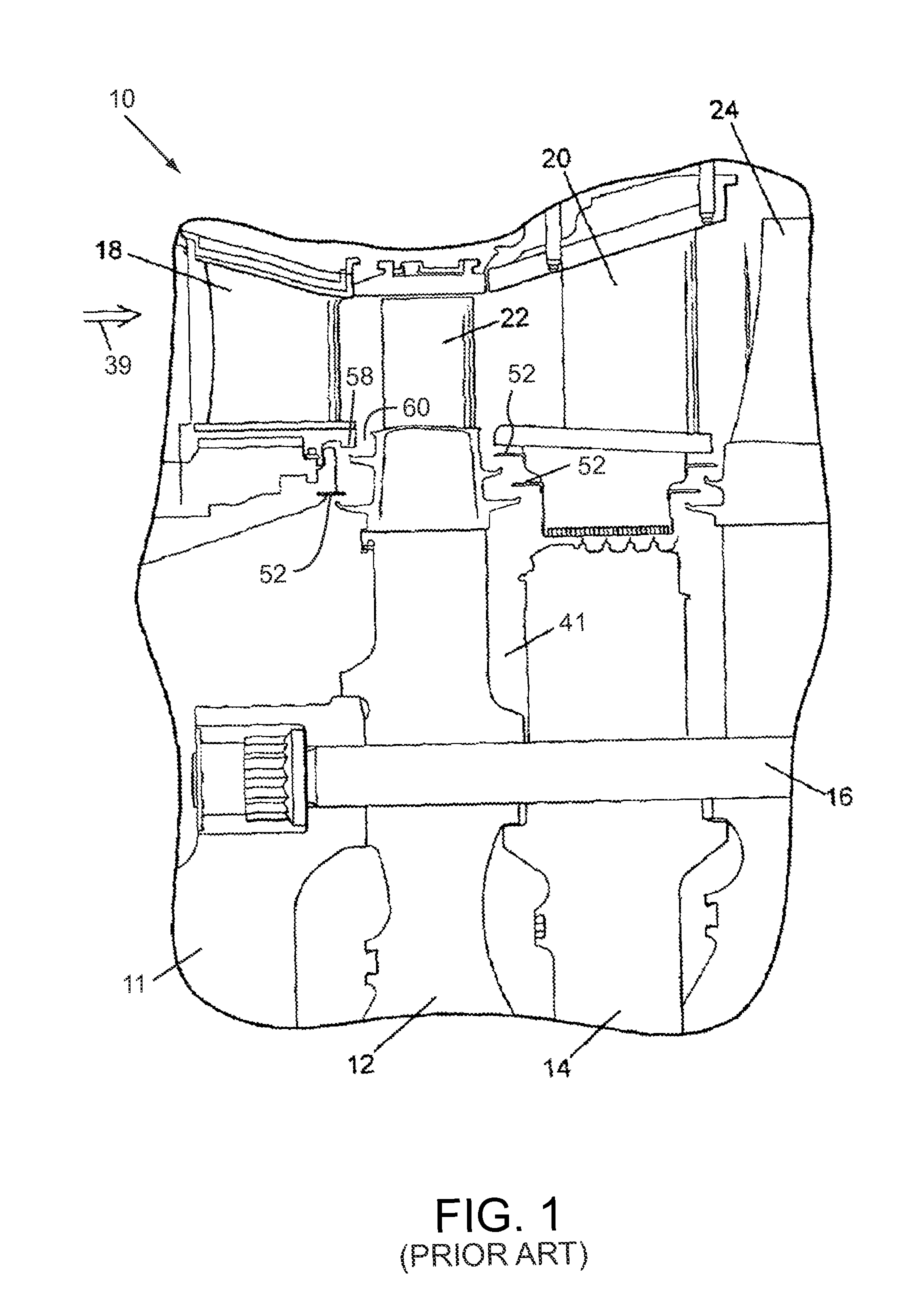
[0020]FIG. 1 schematically illustrates a section of a gas turbine, generally designated 10, including a rotor 11 having axially spaced rotor wheels 12 and spacers 14 joined one to the other by a plurality of circumferentially spaced, axially-extending bolts 16. Turbine 10 includes various stages having nozzles, for example, first-stage nozzles 18 and second-stage nozzles 20 having a plurality of circumferentially-spaced, stationary stator blades. Between the nozzles and rotating with the rotor and rotor wheels 12 are a plurality of rotor blades, e.g., first and second-stage rotor blades or buckets 22 and 24, respectively.

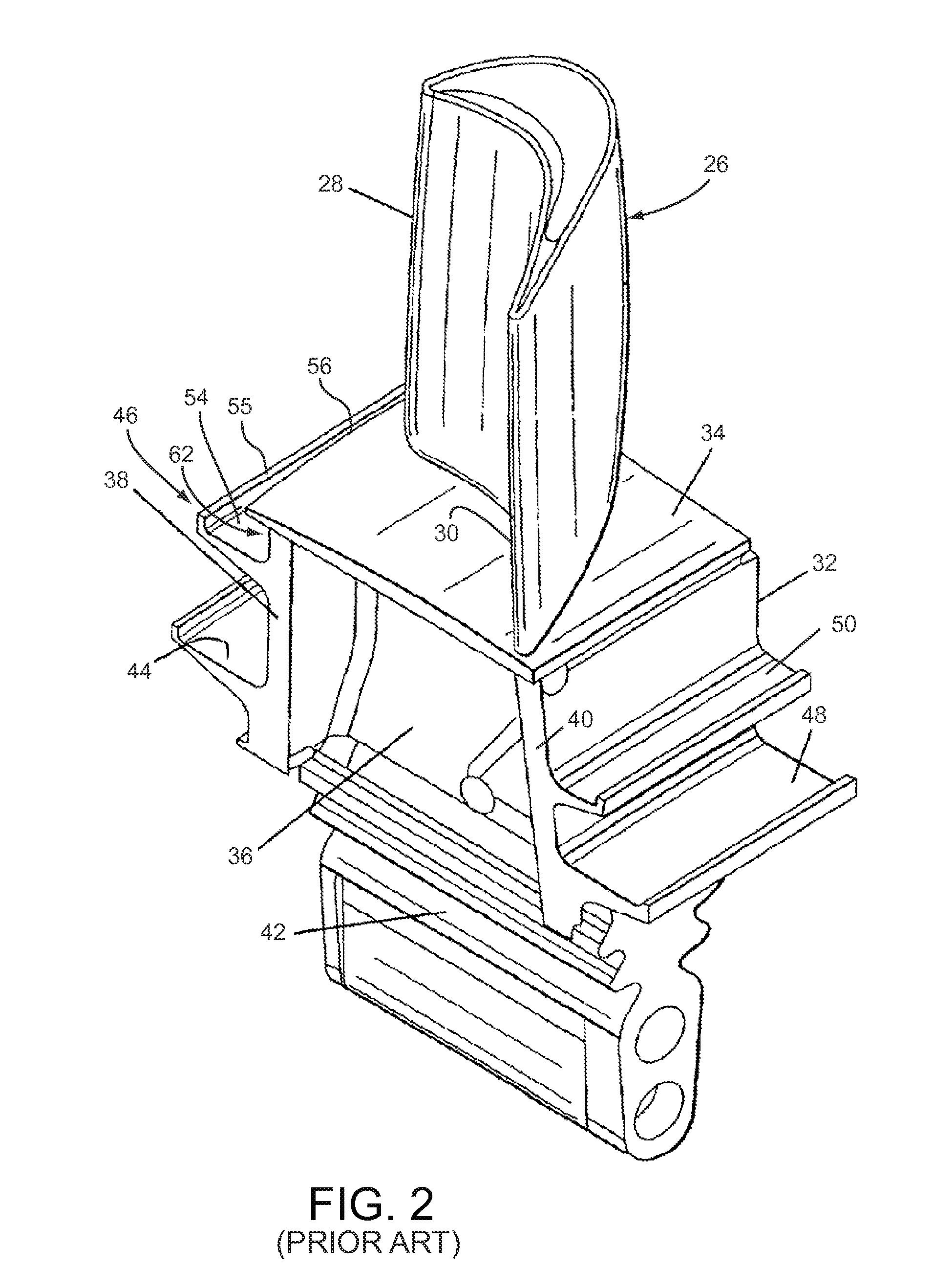
[0021]Referring to FIG. 2, each bucket (for example, bucket 22 of FIG. 1) includes an airfoil 26 having a leading edge 28 and a trailing edge 30, mounted on a shank 32 including a platform 34 and a shank pocket 36 having integral cover plates 38, 40. A dovetail 42 is adapted for connection with generally corresponding dovetail slots formed on the rotor wheel 12 (FIG...


PUM


Abstract

A turbine bucket includes a radially inner mounting portion, a shank radially outward of the mounting portion, a radially outer airfoil and a substantially planar platform radially between the shank, and the airfoil. At least one axially-extending angel wing seal flange is formed on a leading end of the shank forming a circumferentially extending trench cavity along the leading edge of the shank, radially between an underside of the platform leading edge and the angel wing seal flange. A plurality of substantially radially-extending purge air holes are formed in the angel wing seal flange, adapted to fluidly connect a turbine rotor wheel space cavity with the trench cavity and thereby supply purge air to the outer surface of the angel wing seal flange.

Description

BACKGROUND OF THE INVENTION[0001]The present invention relates generally to rotary machines and, more particularly, to the control of forward wheel space cavity purge flow and combustion gas flow at the leading angel wing seals on a gas turbine bucket.[0002]A typical turbine engine includes a compressor for compressing air that is mixed with fuel. The fuel-air mixture is ignited in a combustor to generate hot, pressurized combustion gases in the range of about 1100° C. to 2000° C. that expand through a turbine nozzle, which directs the flow to high and low-pressure turbine stages thus providing additional rotational energy to, for example, drive a power-producing generator.[0003]More specifically, thermal energy produced within the combustor is converted into mechanical energy within the turbine by impinging the hot combustion gases onto one or more bladed rotor assemblies. Each rotor assembly usually includes at least one row of circumferentially-spaced rotor blades or buckets. Eac...

Claims


Application Information

Patent Timeline
Patent Type & Authority Patents(United States)
IPC IPC(8): F03B11/00F01D11/00F01D11/04
CPCF01D11/001F01D11/04
Inventor INGRAM, CLINT LUIGIE
Owner GENERAL ELECTRIC CO
Why Eureka
Try Eureka