Turbocharger and variable-nozzle cartridge therefor

a variable-nozzle, turbocharger technology, applied in the direction of positive displacement liquid engines, liquid fuel engines, piston pumps, etc., can solve the problems of reducing the efficiency of the turbine and hence the overall performance of the turbocharger, and the clearance effect is particularly harmful at low engine speed, so as to achieve the effect of reducing the performance penalty due to the clearance of the vane at low engine speed and achieving the effect of performance benefi

Active Publication Date: 2015-03-17
GARRETT TRANSPORATION I INC
View PDF13 Cites 5 Cited by
  • Summary
  • Abstract
  • Description
  • Claims
  • Application Information

AI Technical Summary

Benefits of technology

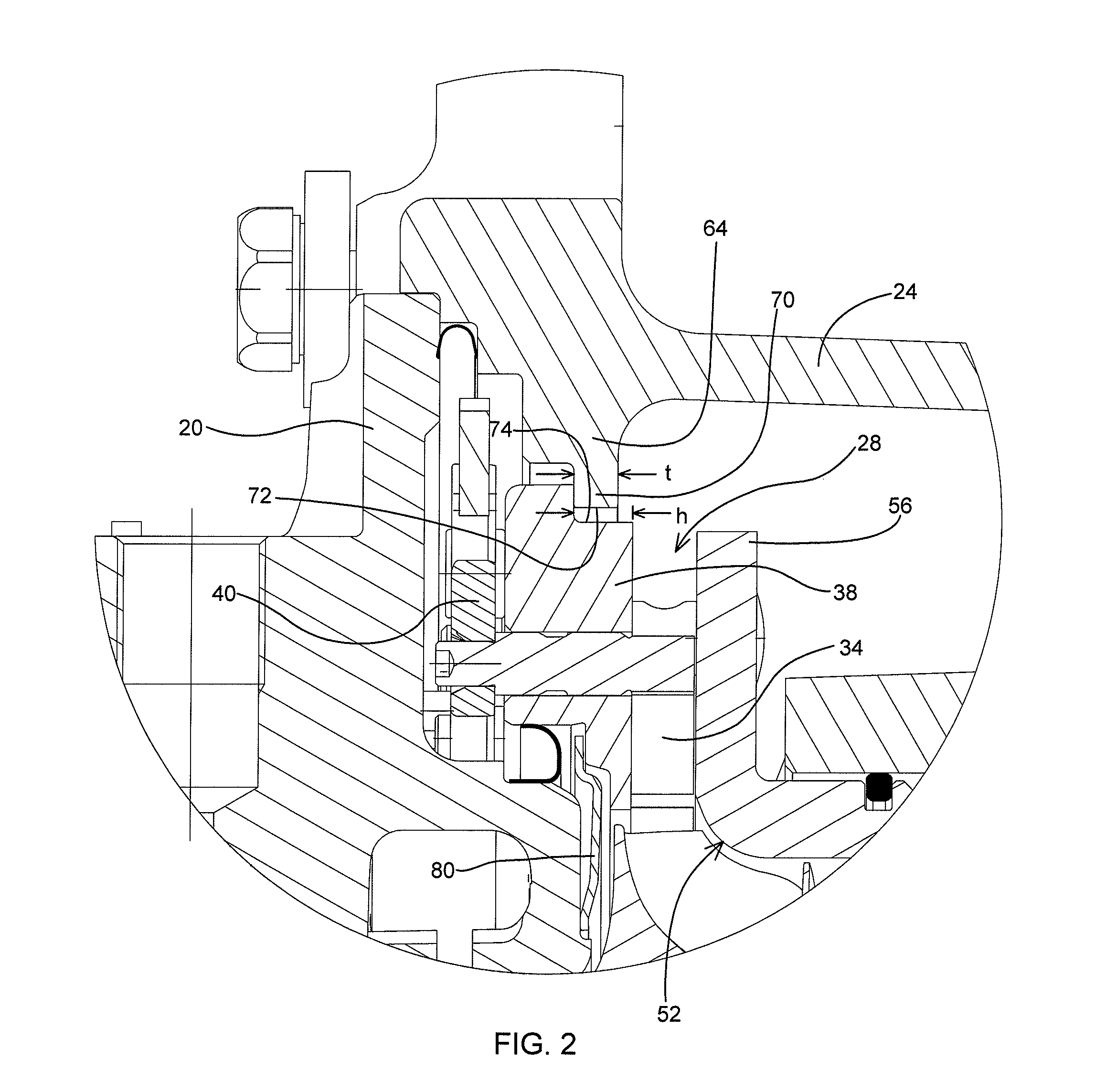
[0005]The present invention is based on a discovery that the performance penalty due to vane clearance at low engine speeds can be substantially reduced by arranging a “negative” step in the nozzle flow path radially outwardly of the vanes. By “negative” step, it is meant that the step is facing radially outwardly so as to be impinged by exhaust gas flowing radially inwardly through the nozzle. It has been found that such a negative step has a performance benefit similar to that achieved by reducing the vane clearance in the absence of such a step, but without incurring the problems that can arise when the vane clearance is reduced (e.g., vane binding because of thermal expansion / contraction effects).

Problems solved by technology

One of the challenges in boosting engine performance with a turbocharger is achieving a desired amount of engine power output throughout the entire operating range of the engine.
Clearances between the ends of the vanes and the adjacent nozzle walls generally have a deleterious effect on turbine efficiency and hence overall turbocharger performance.
This clearance effect is particularly harmful at low engine speeds.

Method used


Image

  • Turbocharger and variable-nozzle cartridge therefor
  • Turbocharger and variable-nozzle cartridge therefor
  • Turbocharger and variable-nozzle cartridge therefor

Examples


Embodiment Construction

[0015]The present inventions now will be described more fully hereinafter with reference to the accompanying drawings, in which some but not all embodiments of the inventions are shown. Indeed, these inventions may be embodied in many different forms and should not be construed as limited to the embodiments set forth herein; rather, these embodiments are provided so that this disclosure will satisfy applicable legal requirements. Like numbers refer to like elements throughout.

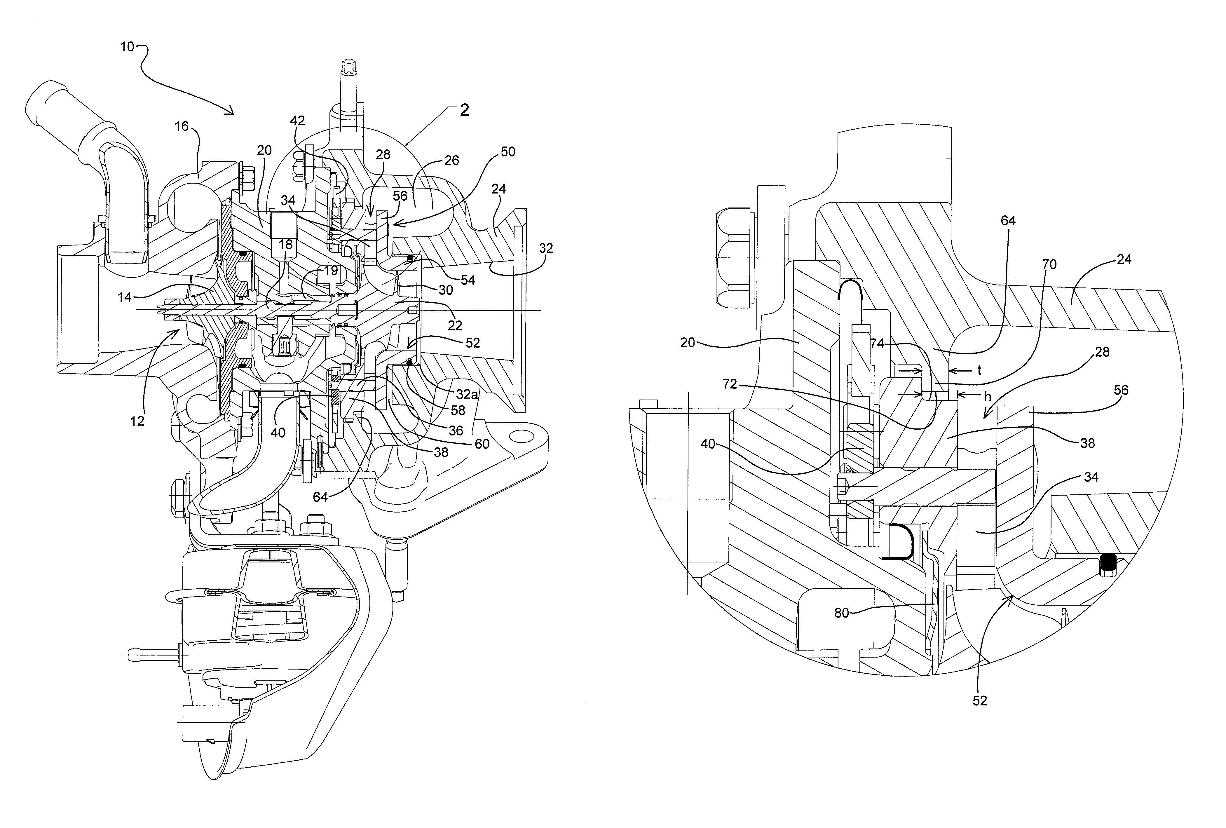
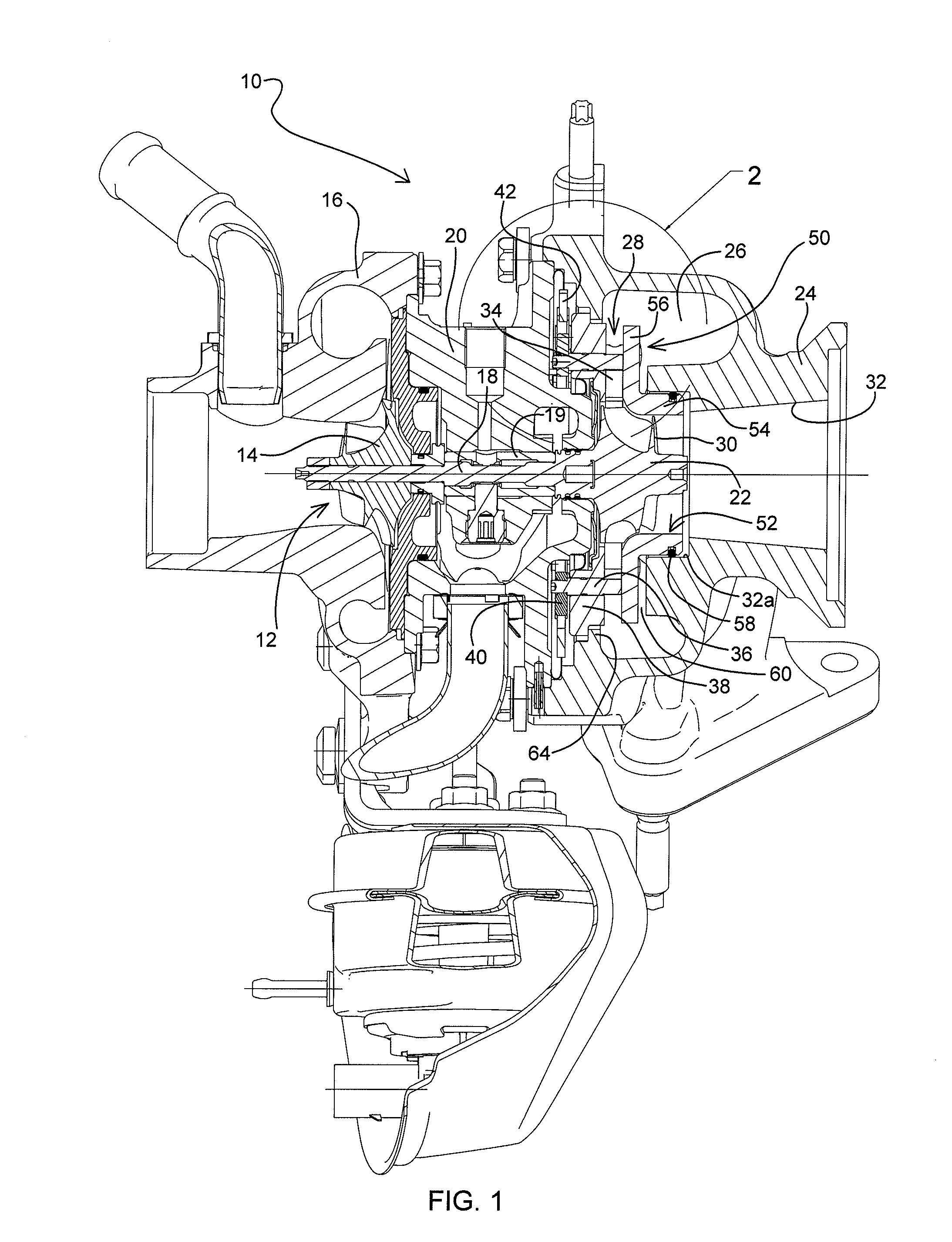
[0016]A turbocharger 10 in accordance with one embodiment of the invention is illustrated in cross-sectional view in FIG. 1. The turbocharger comprises a compressor 12 having a compressor wheel or impeller 14 mounted in a compressor housing 16 on one end of a rotatable shaft 18. The shaft is supported in bearings 19 mounted in a center housing 20 of the turbocharger. The shaft 18 is rotated by a turbine wheel 22 mounted on the other end of the shaft 18 from the compressor wheel, thereby rotatably driving the co...


PUM


Abstract

A variable-vane assembly for a turbocharger includes an annular nozzle ring supporting an array of rotatable vanes, an insert having a tubular portion sealingly received into the bore of the turbine housing and having a nozzle portion extending radially out from one end of the tubular portion and being axially spaced from the nozzle ring with the vanes therebetween, and an annular retainer ring disposed radially outward of the nozzle ring and extending generally radially inwardly. The nozzle ring's face is stepped, and a radially inner edge of the retainer ring engages the face of the nozzle ring radially outward of the step, the radially inner edge of the retainer ring having an axial thickness that is less than the step height such that a remaining portion of the step is presented to the exhaust gas flowing through the nozzle.

Description

BACKGROUND OF THE INVENTION[0001]The present invention relates to turbochargers having a variable-nozzle turbine in which an array of movable vanes is disposed in the nozzle of the turbine for regulating exhaust gas flow into the turbine.[0002]An exhaust gas-driven turbocharger is a device used in conjunction with an internal combustion engine for increasing the power output of the engine by compressing the air that is delivered to the air intake of the engine to be mixed with fuel and burned in the engine. A turbocharger comprises a compressor wheel mounted on one end of a shaft in a compressor housing and a turbine wheel mounted on the other end of the shaft in a turbine housing. Typically the turbine housing is formed separately from the compressor housing, and there is yet another center housing connected between the turbine and compressor housings for containing bearings for the shaft. The turbine housing defines a generally annular chamber that surrounds the turbine wheel and ...

Claims


Application Information

Patent Timeline
Patent Type & Authority Patents(United States)
IPC IPC(8): F04D13/04F01D17/16F02C6/12
CPCF01D17/16F02C6/12F01D17/165
Inventor MAILFERT, JULIENMORAND, NICOLASBELTRAMI, CALOGERO
Owner GARRETT TRANSPORATION I INC
Why Eureka
Try Eureka