Apparatus and method of measuring terahertz wave

a technology of terahertz wave and apparatus, which is applied in the field of apparatus and a method of measuring terahertz wave, can solve the problems of increasing the vibration effect of the stage of the optical delay unit, the oscillation of the optical axis of the excitation light, and the difficulty of real-time acquisition of such pulses, etc., to suppress the spurious spectrum, increase the measurement bandwidth, and suppress the signal components

Inactive Publication Date: 2015-03-17
CANON KK
View PDF4 Cites 0 Cited by
  • Summary
  • Abstract
  • Description
  • Claims
  • Application Information

AI Technical Summary

Benefits of technology

[0008]In the method according to one aspect of the invention, the speed pattern used to drive the optical delay unit is changed for each measurement of the time-domain waveform, and measurement results are averaged. Changing the speed pattern results in a change in sampling time intervals at which data is acquired to reproduce the time-domain waveform of the terahertz wave. The time-domain waveform of the terahertz wave reproduced does not depend on the sampling time intervals. However, the change in the sampling time interval causes a change in shape of a signal component having substantially no relation with the terahertz wave. This property makes it possible to suppress the signal components having the small relation with the terahertz wave by averaging data obtained for various speed patterns. Thus, it becomes possible to suppress a spurious spectrum superimposed on a frequency spectrum and it becomes possible to increase a measurement bandwidth.

Problems solved by technology

It is generally difficult to acquire such a pulse in real time because of the slow response that current electronics have with respect to the speed of THz waves.
In the THz-TDS apparatus, an increase in the measurement sensitivity can result in an increase in effects of a vibration of the stage of the optical delay unit.
More specifically, the vibration of the stage used in the optical delay unit causes the optical axis of the excitation light to swing.
This causes a change in the amount of light per unit area that strikes the small gaps of the photoconductive device.
Such a spurious spectrum can limit a measurement bandwidth of the measurement apparatus and can cause a reduction in analysis performance thereof.

Method used


Image

  • Apparatus and method of measuring terahertz wave
  • Apparatus and method of measuring terahertz wave
  • Apparatus and method of measuring terahertz wave

Examples


Embodiment Construction

[0027]In an apparatus and a method of acquiring a time-domain waveform of a terahertz wave using time-domain spectroscopy according to an aspect of the present invention, a plurality of time-domain waveforms are acquired by driving an optical delay unit according to a plurality of different speed patterns, and a final time-domain waveform is acquired by averaging the plurality of time-domain waveforms. A basic configuration and a spirit of the apparatus and the method of acquiring the time-domain waveform of the terahertz wave using the time-domain spectroscopy according to an aspect of the invention have been described above.

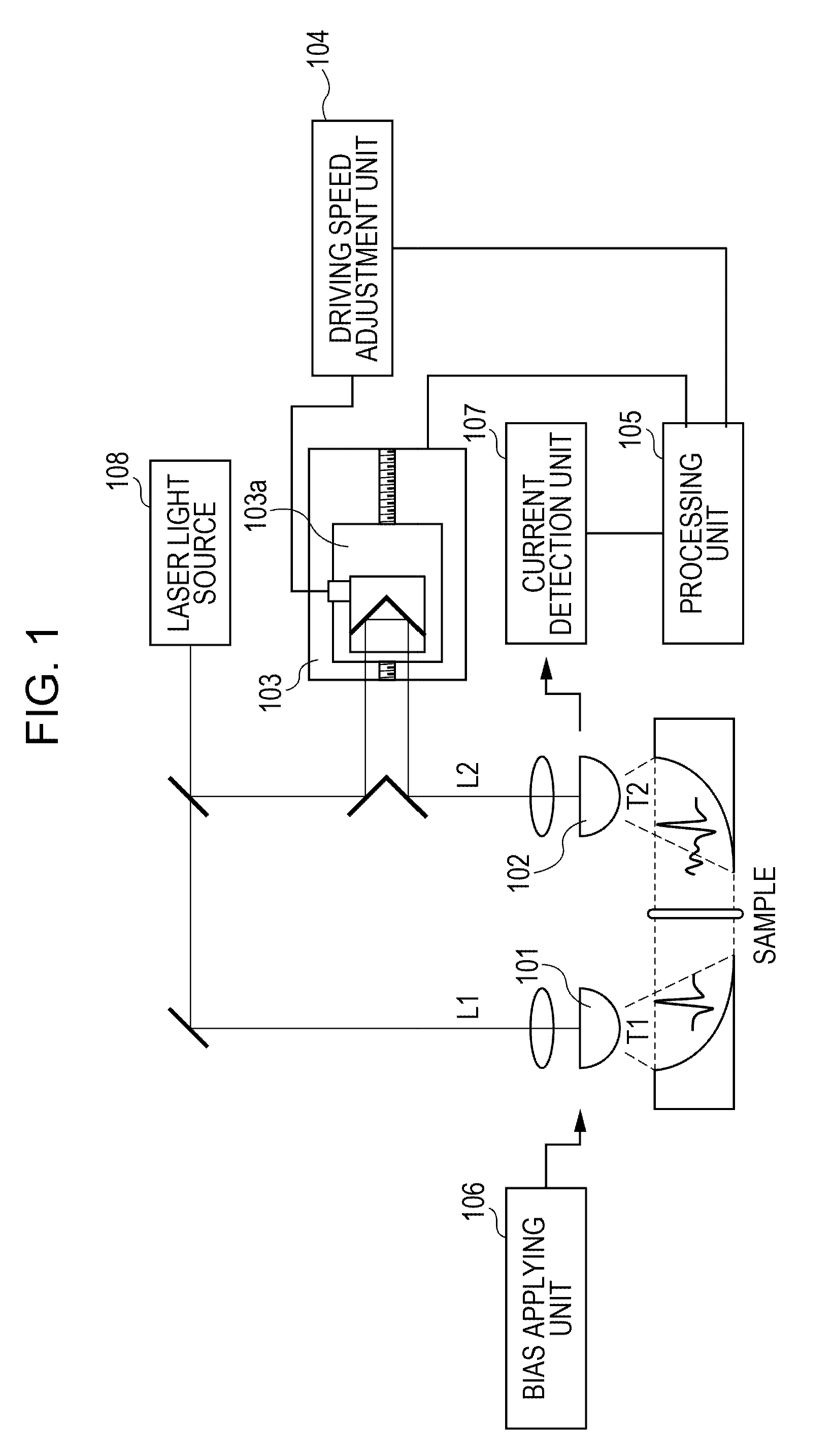
[0028]Next, specific embodiments of the invention are described below with reference to the accompanying drawings. FIG. 1 is a diagram illustrating an example of a configuration of a terahertz wave measurement apparatus according to an embodiment of the invention. As shown in FIG. 1, the apparatus includes a generating unit 101, a detection unit 102, an optical...


PUM

PropertyMeasurementUnit
repetition frequencyaaaaaaaaaa
optical path lengthaaaaaaaaaa
cutoff frequencyaaaaaaaaaa

Abstract

A time-domain waveform of a terahertz wave is measured by a method based on time-domain spectroscopy by using an optical delay unit to adjust an optical path length along which excitation light propagates thereby adjusting a difference between a time at which the excitation light arrives at a generating unit configured to generate the terahertz wave and a time at which the excitation light arrives at a detection unit configured to detect the terahertz wave. The optical delay unit is driven according to a first speed pattern to acquire a first time-domain waveform. The optical delay unit is then driven according to a second speed pattern different from the first speed pattern to acquire a second time-domain waveform. The first time-domain waveform and the second time-domain waveform are averaged.

Description

BACKGROUND OF THE INVENTION[0001]1. Field of the Invention[0002]The present invention relates to an apparatus and a method of measuring a terahertz wave, and more particularly, to an apparatus and a method of measuring a terahertz wave in a time domain. Hereinafter, such as an apparatus will be also referred to as a THz TDS (Time Domain Spectroscopy) apparatus.[0003]2. Description of the Related Art[0004]A terahertz wave is an electromagnetic wave with a frequency in an arbitrary frequency band within a range from 0.03 THz to 30 THz. This frequency range includes many frequencies or bands of frequency at which characteristic absorption occurs due to structures or states of substances such as biological molecules. This feature is usable to nondestructively analyze or identify a substance, and associated techniques have been developed. One example of a predicted application is a safety imaging technique usable instead of an X-ray imaging technique. Another example of a predicted appli...

Claims


Application Information

Patent Timeline
Patent Type & Authority Patents(United States)
IPC IPC(8): G01J5/12G01N21/35G01J3/42G01N21/3586
CPCG01N21/3586G01J3/42G01N2201/06113G01N2201/066
Inventor ITSUJI, TAKEAKI
Owner CANON KK
Why Eureka
Try Eureka