Methods, apparatuses, systems and software for focusing a camera on an object in any of a plurality of zones using graphics overlaid on a display

a technology of graphics and overlays, applied in the field of motion picture or cinematic camera focusing, can solve the problems of shallow depth of field of lens, inability to use pre-set focus reference marks, and inability to achieve acceptable sharp focus using these conventional methods

Active Publication Date: 2015-03-17
PRESTON HOWARD
View PDF8 Cites 20 Cited by
  • Summary
  • Abstract
  • Description
  • Claims
  • Application Information

AI Technical Summary

Benefits of technology

[0020]The present invention overcomes disadvantages of autofocus devices by providing a mechanism for the user to manually adjust the focus on moving subjects with high accuracy, as well as providing an autofocus function in circumstances when manual adjustment may be challenging or impractical due to the motion of a subject or object being too fast or unpredictable. The present invention (and in particular, the overlaid graphics) make it possible for the user to switch between manual and autofocus modes smoothly. The present invention advantageously provides a method for the user to accurately focus the shooting lens of or on a motion picture camera by observing graphics overlaid on the image captured by the camera. The overlaid graphics can indicate both the direction and magnitude of distances, as measured along the optical axis of the camera lens, between the plane of focus of the camera lens and a plethora of subjects within a plurality of detection zones within the detection field of a distance measuring device.
[0023]The present invention also advantageously provides a device or apparatus that comprises a measuring device that measures each of a plurality of distances from itself to each of a plurality of subjects in a field of view of a camera (e.g., within multiple detection zones in the field of view) simultaneously; a data processing device that can correct the distances measured by the distance measuring device for the offset from itself to the center of the camera image plane, and can calculate the distances along the optical axis of the camera lens from the image plane to the plurality of subjects, and thereby calculate the lens focus setting for each of the plurality of subjects; and a video overlay, data processing, and communication unit that generates graphics indicating the horizontal field of detection and position for each detection zone of and / or subject or object of interest in the detection field of the distance measuring device, and can determine and display the lens focus settings for the subjects detected in the detection field and / or each detection zone according to information provided by the data processing device.

Problems solved by technology

In many situations, the focus puller cannot achieve acceptably sharp focus using these conventional methods.
For example, when the camera is moving during the process of shooting a scene, it is often not possible to use pre-set focus reference marks, as the path taken by the camera may not be predictable.
In other situations, the depth of field of the lens is so shallow that the focus setting cannot be reliably estimated by the focus puller, even when reference marks are available.
However, the monitor can only show the degree to which the image appears to be in focus.
There have been a number of challenges to focusing a camera (or image captured by the camera) using a video monitor.
For example, once unclear or “buzzed” focus is observed, it is often too late to maintain or bring back focus, especially when subjects in the field of view of the camera are in motion.
Sometimes it can be difficult to tell whether one must pull forward or backward to correct the focus.
Peaking, or making the edges of objects within the image more visible (e.g., by increasing the contrast or color of the edges, or making the edges shimmer) does not provide much critical focusing information.
Also, on many episodic TV series, there isn't sufficient room on set for the focus pullers, and they often work outside the set.
However, an off-axis target present in a side lobe may be detected and may cause incorrect focus.
This characteristic can result in the ultrasonic DMD indicating erroneous distance especially if one or more targets are near the side-lobes.
The single detection zone characteristic of ultrasonic DMD's limits the ability of the focus puller to discriminate between multiple targets located within the single detection zone of the ultrasonic DMD.
An additional disadvantage of devices that provide a digital display of the distance to a subject is that the user needs some time to interpret the difference between the distance display of the DMD and the present setting of the lens distance prior to changing the lens focus setting.
The additional time that the user takes to interpret the digital information increases the difficulty of maintaining sharp focus in situations where the either the subject or camera is moving quickly.
For this reason, LR devices may be well-suited for autofocusing, but disadvantageous for manual operation.
The disadvantage of auto-focus devices relative to manual focus control is that the rate at which the lens focus setting matches the subject distance is fixed by the settings of an automatic closed loop servo in auto-focus devices.
This disadvantage of autofocus devices is especially apparent when focus is changed between subjects.
More specifically, with reference to the movement of the subjects in certain contexts, settings or situations, a mechanical appearance to the focus change may be artistically undesirable.

Method used


Image

  • Methods, apparatuses, systems and software for focusing a camera on an object in any of a plurality of zones using graphics overlaid on a display
  • Methods, apparatuses, systems and software for focusing a camera on an object in any of a plurality of zones using graphics overlaid on a display
  • Methods, apparatuses, systems and software for focusing a camera on an object in any of a plurality of zones using graphics overlaid on a display

Examples


Embodiment Construction

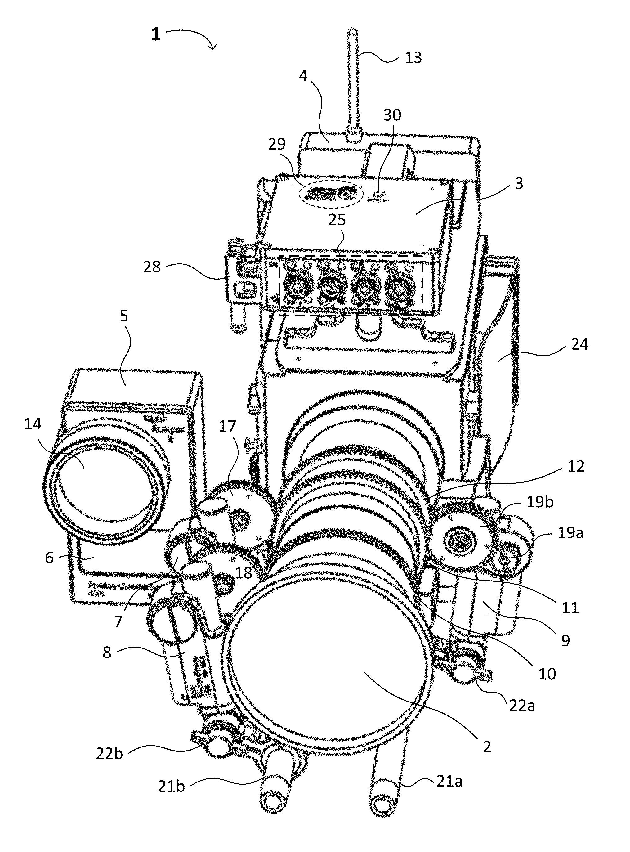
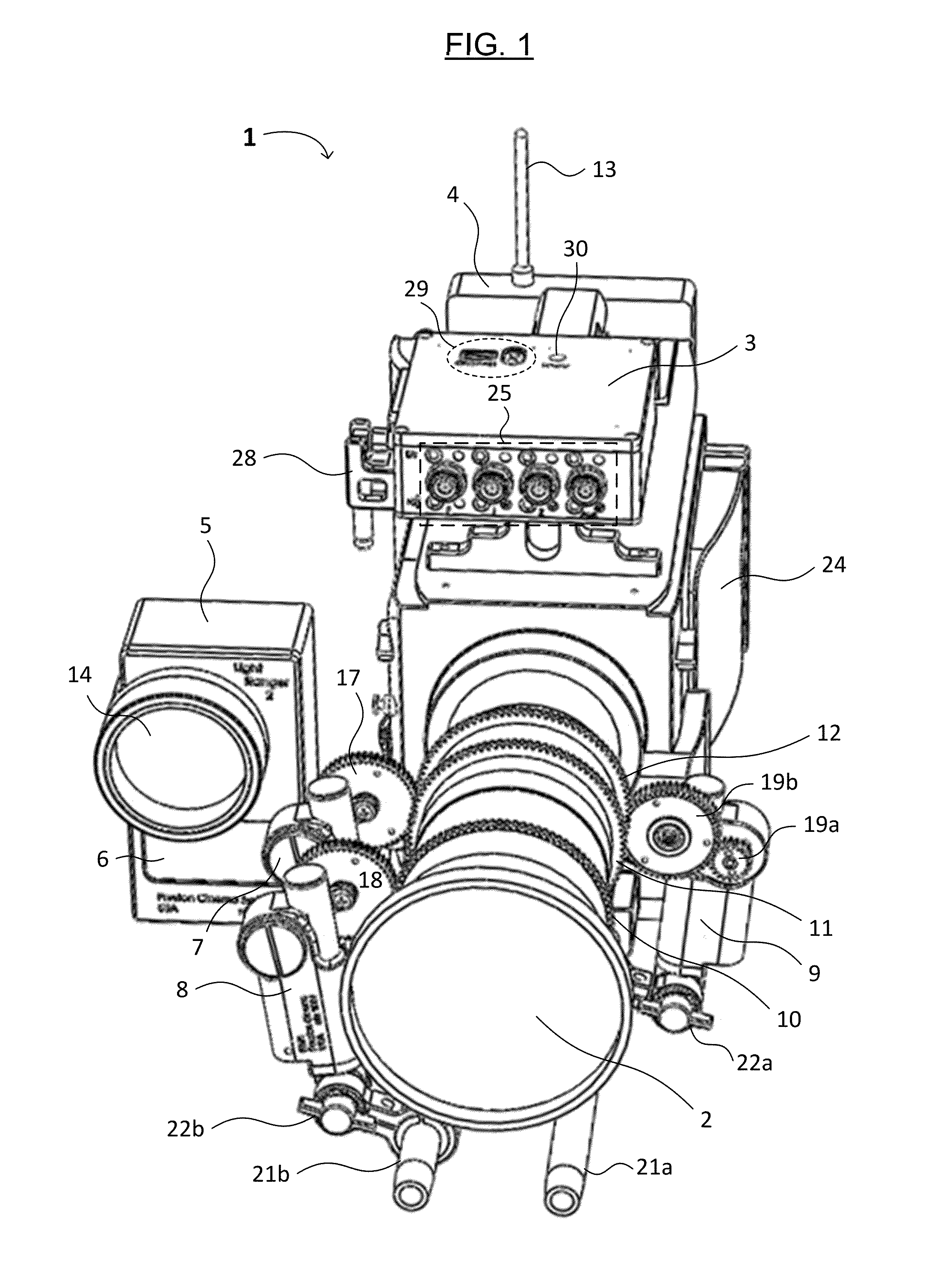
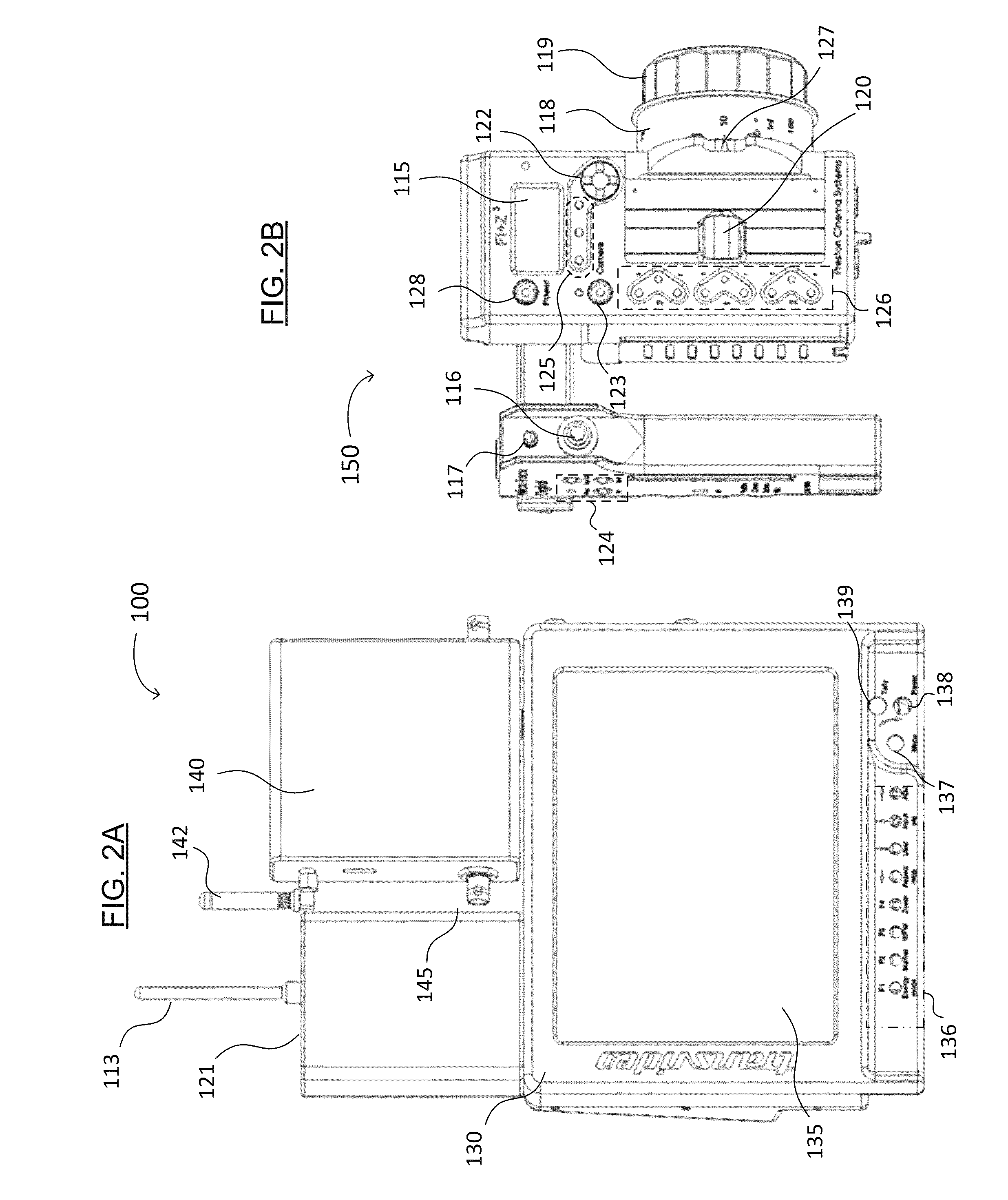
[0034]Reference will now be made in detail to various embodiments of the invention, examples of which are illustrated in the accompanying drawings. While the invention will be described in conjunction with the following embodiments, it will be understood that the descriptions are not intended to limit the invention to these embodiments. On the contrary, the invention is intended to cover alternatives, modifications and equivalents that may be included within the spirit and scope of the invention as defined by the appended claims. Furthermore, in the following detailed description, numerous specific details are set forth in order to provide a thorough understanding of the present invention. However, it will be readily apparent to one skilled in the art that the present invention may be practiced without these specific details. In other instances, well-known methods, procedures, components, and circuits have not been described in detail so as not to unnecessarily obscure aspects of th...


PUM


Abstract

Methods, apparatuses, systems and software for focusing a camera are disclosed. The camera focusing system includes a distance measuring device, a video receiver that receives video / images, a graphics overlay unit, and a monitor. The distance measuring device includes an emitter that emits a radiation beam, a detector that detects reflected radiation, and logic that determines and processes distance information for subject(s) or object(s) in detection zones from the reflections. The graphics overlay unit receives video / image information from the video receiver and the distance information from the distance measuring device, and includes a video overlay and data processing unit that generates graphics indicating a field of detection and position for each detection zone and a direction and / or magnitude of a change in focus setting(s) to bring subjects or objects within each detection zone into focus. The monitor displays the video / image and the graphics overlaid thereon.

Description

FIELD OF THE INVENTION[0001]The present invention generally relates to the field of focusing a motion picture or cinematic camera. More specifically, embodiments of the present invention pertain to methods, apparatuses, systems and software for focusing a motion picture camera.DISCUSSION OF THE BACKGROUND[0002]Conventionally, the focus of a motion picture camera lens is set manually to a distance where the plane of focus of the lens closely coincides with the location of a photographic subject. The camera lenses have focus distance calibrations that correspond to the distance from the image plane of the camera to the focus plane. Motion picture cameras may also have an electronic mechanism for delivering the focus distance setting through an electrical interface. The focus puller (e.g., a technician responsible for setting the focus of the camera lens) can adjust the camera lens to the subject distance by estimating the distance to a photographic subject and setting the focus distan...

Claims


Application Information

Patent Timeline
Patent Type & Authority Patents(United States)
IPC IPC(8): G03B13/00H04N5/232
CPCH04N5/23212H04N23/67H04N23/635
Inventor PRESTON, HOWARD
Owner PRESTON HOWARD
Why Eureka
Try Eureka