Digital self-gated binary counter

a counter circuit and self-gate technology, applied in the field of digital counter circuits, can solve the problems of limited operational frequency, significant increase in dynamic power consumption of digital counters,

Active Publication Date: 2015-03-17
NXP USA INC
View PDF10 Cites 0 Cited by
  • Summary
  • Abstract
  • Description
  • Claims
  • Application Information

AI Technical Summary

Problems solved by technology

All this leads to a significant increase in dynamic power consumption of digital counters, or limited operational frequencies.

Method used


Image

  • Digital self-gated binary counter
  • Digital self-gated binary counter
  • Digital self-gated binary counter

Examples


Embodiment Construction

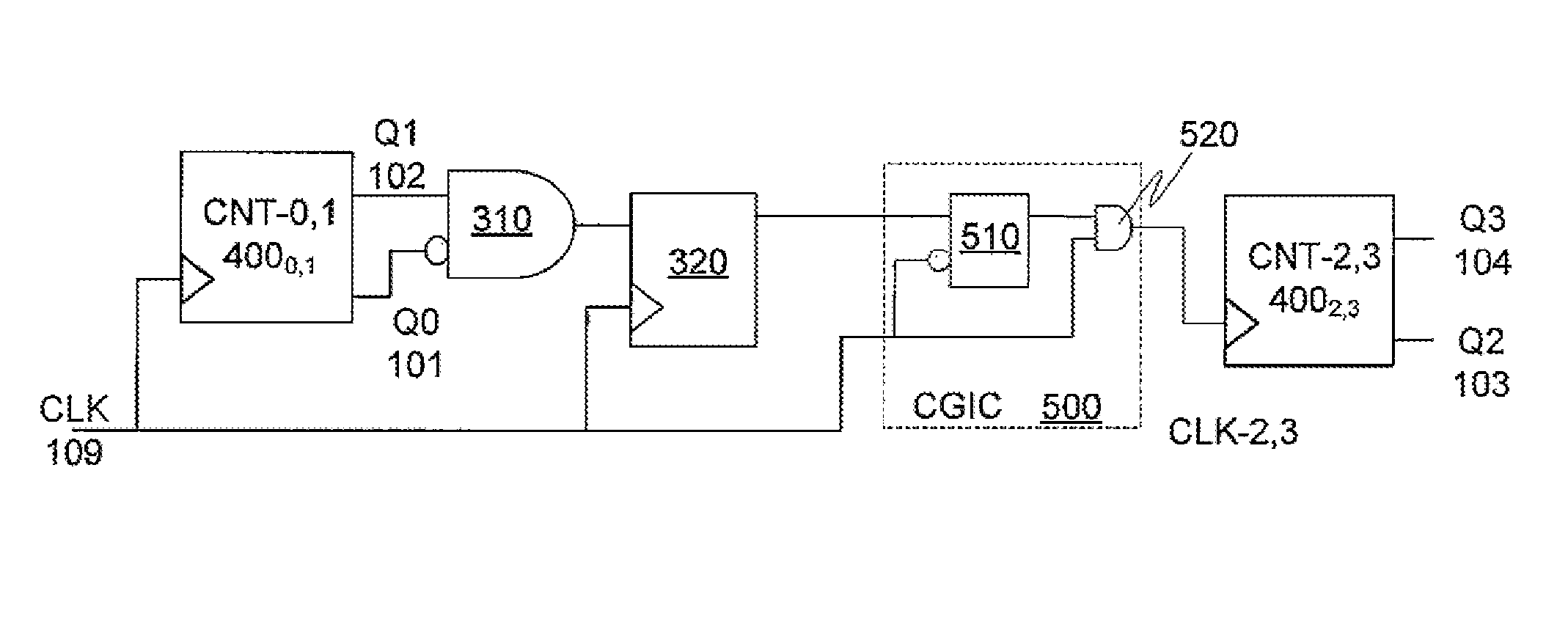
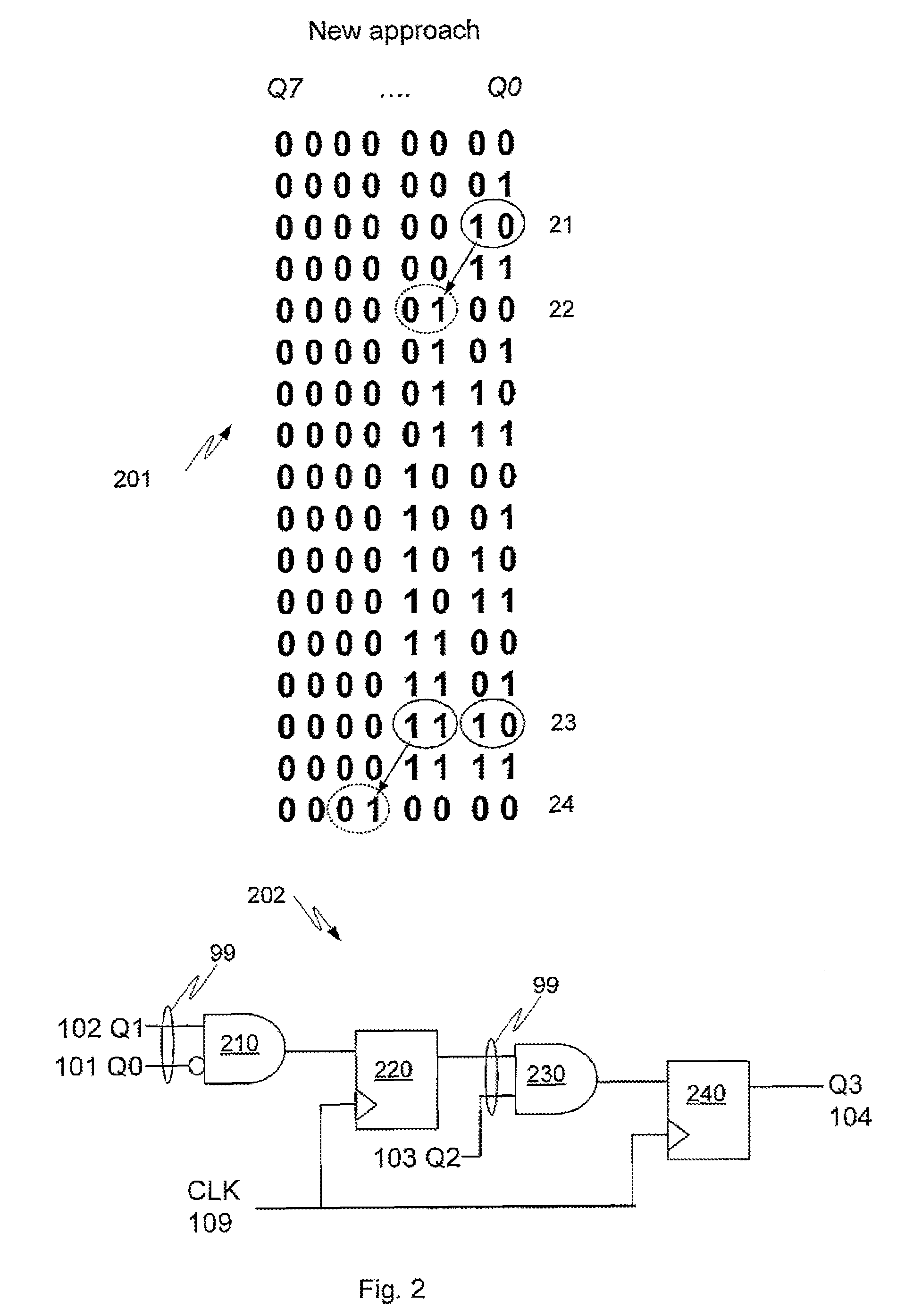
[0022]The present invention provides a binary counter that can operate at high frequency while consuming low dynamic power. Because the illustrated embodiments of the present invention may for the most part, be implemented using electronic components and circuits known to those skilled in the art, details will not be explained in any greater extent than that considered necessary as illustrated above, for the understanding and appreciation of the underlying concepts of the present invention and in order not to obfuscate or distract from the teachings of the present invention.

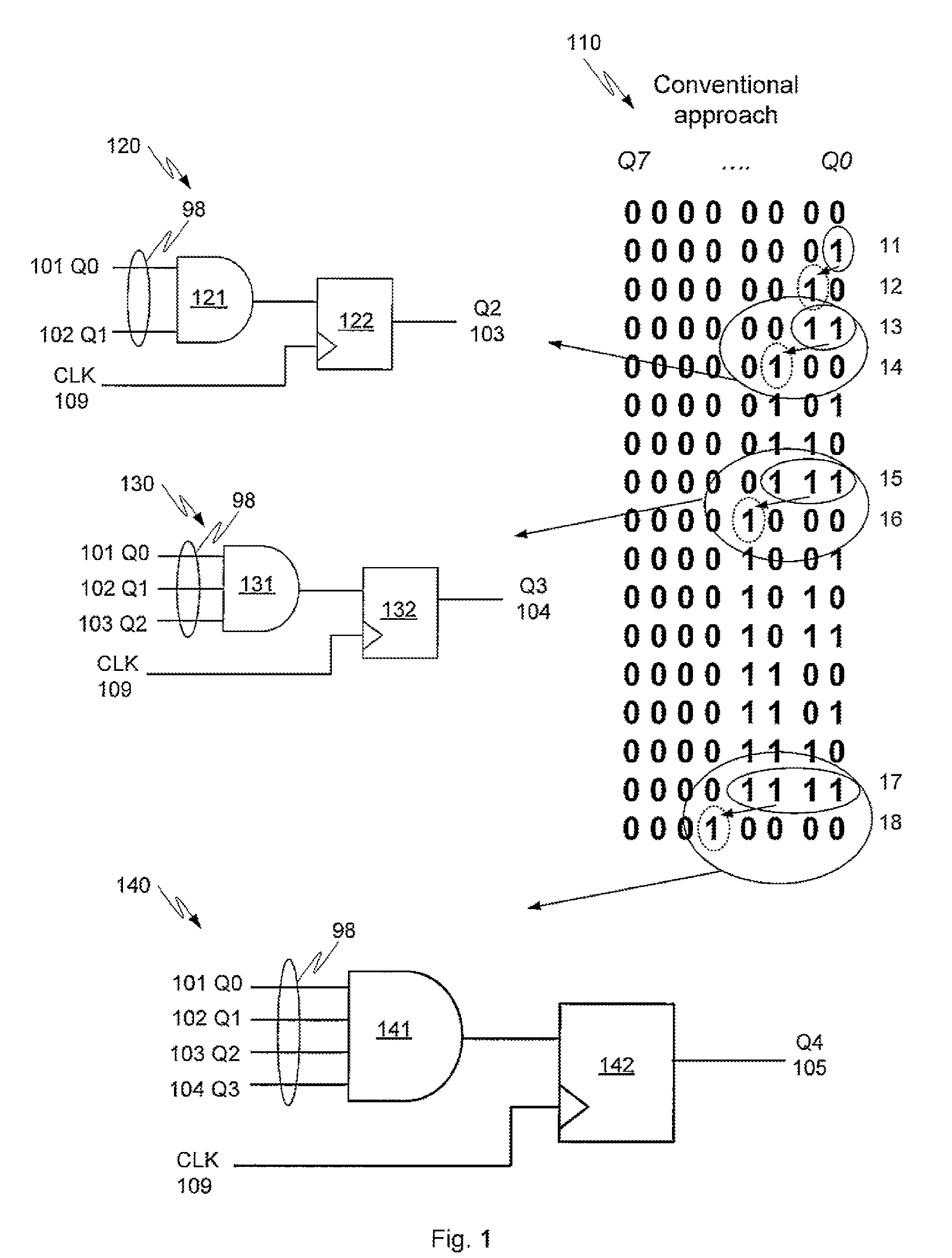
[0023]One way to increase throughput of a digital circuit is to increase operational frequency, but increasing frequency is limited not only by timing closure challenges (e.g., the difficulties in meeting the setup timing check between flip-flops, as the operational frequency increases), but also by increases in dynamic power consumption of the overall digital circuit (e.g., due to the switching losses in the cir...


PUM


Abstract

An n-bit counter is formed from cascading counter sub-modules. The counter includes combinatorial control logic coupled to a lower order counter sub-module. The control logic is arranged to clock gate at least one higher order counter sub-module dependent on a logical combination of outputs of the lower order counter sub-module and where the control logic uses pipelining to store at least one previous control logic output for use in determining a later control logic output.

Description

BACKGROUND OF THE INVENTION[0001]The present invention relates to digital counter circuits and, more particularly, to digital binary counter circuits.[0002]A digital binary counter circuit is a logic circuit used for counting the number of times a particular event has occurred with respect to a base clock signal (CLK). A counter may be any arbitrary length (i.e., up to n-bits in length), with the maximum number of countable events being related to the counter bit length. For example, an 8-bit counter can count up to 256 events (i.e., up to 28), while a 16-bit counter can count up to 65,536 events (i.e., up to 216), etc.[0003]Counter circuits are used in many integrated circuit designs, for example in an System on Chip (SoC), and may be formed of a set of sequential elements, such as flip-flops, operatively coupled together with suitable combinatorial control logic. As more features are being integrated into digital circuits, such as SoC's, the number of flip-flops used for the count...

Claims


Application Information

Patent Timeline
Patent Type & Authority Patents(United States)
IPC IPC(8): H03K23/00H03K21/12H03K21/38H03K23/40H03K23/58
CPCH03K23/40H03K23/58H03K21/38H03K21/12H03K21/00H03K23/00
Inventor GUPTA, NAMANAGARWAL, AMOLGOYAL, GAURAV
Owner NXP USA INC
Why Eureka
Try Eureka