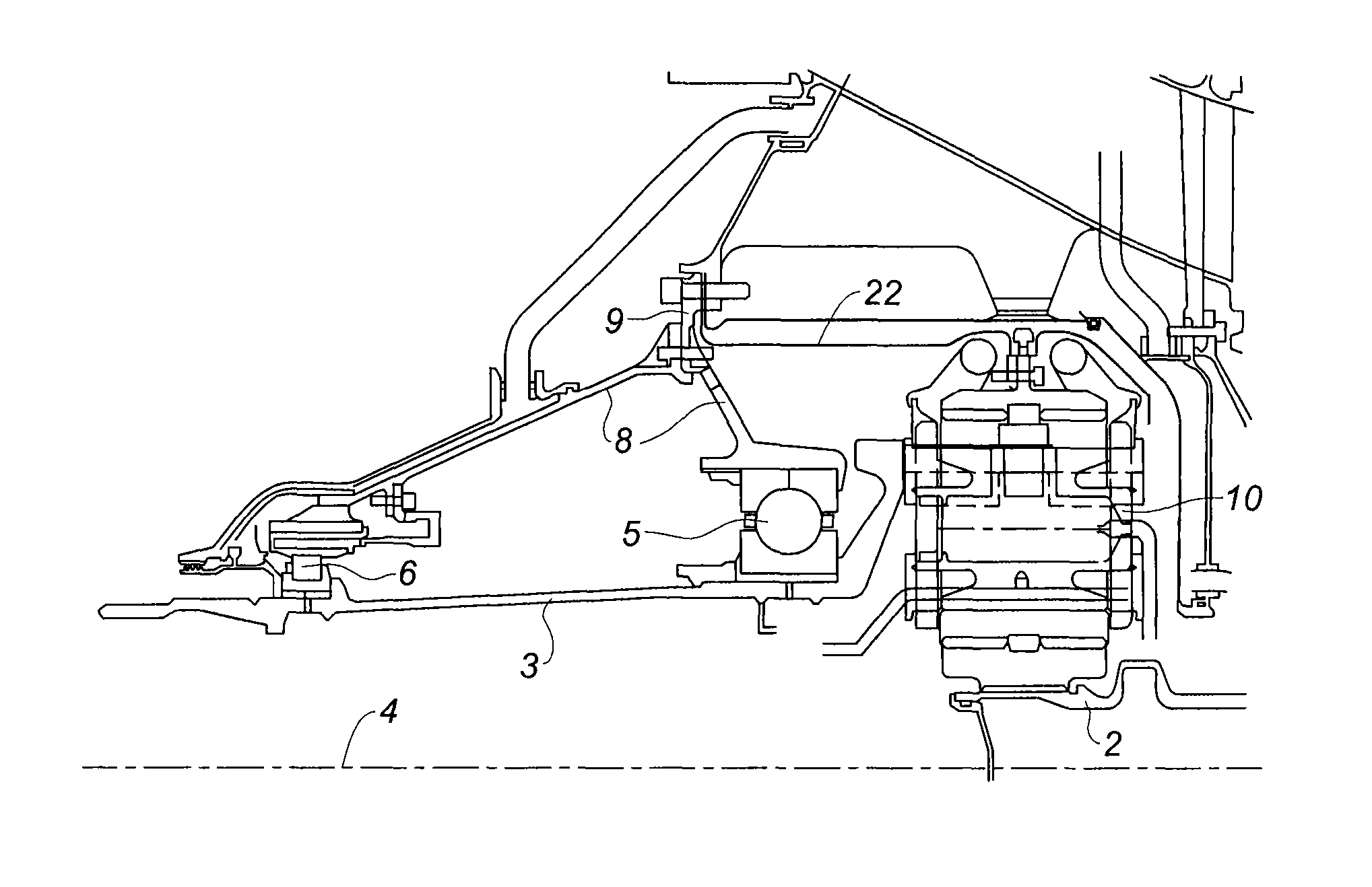
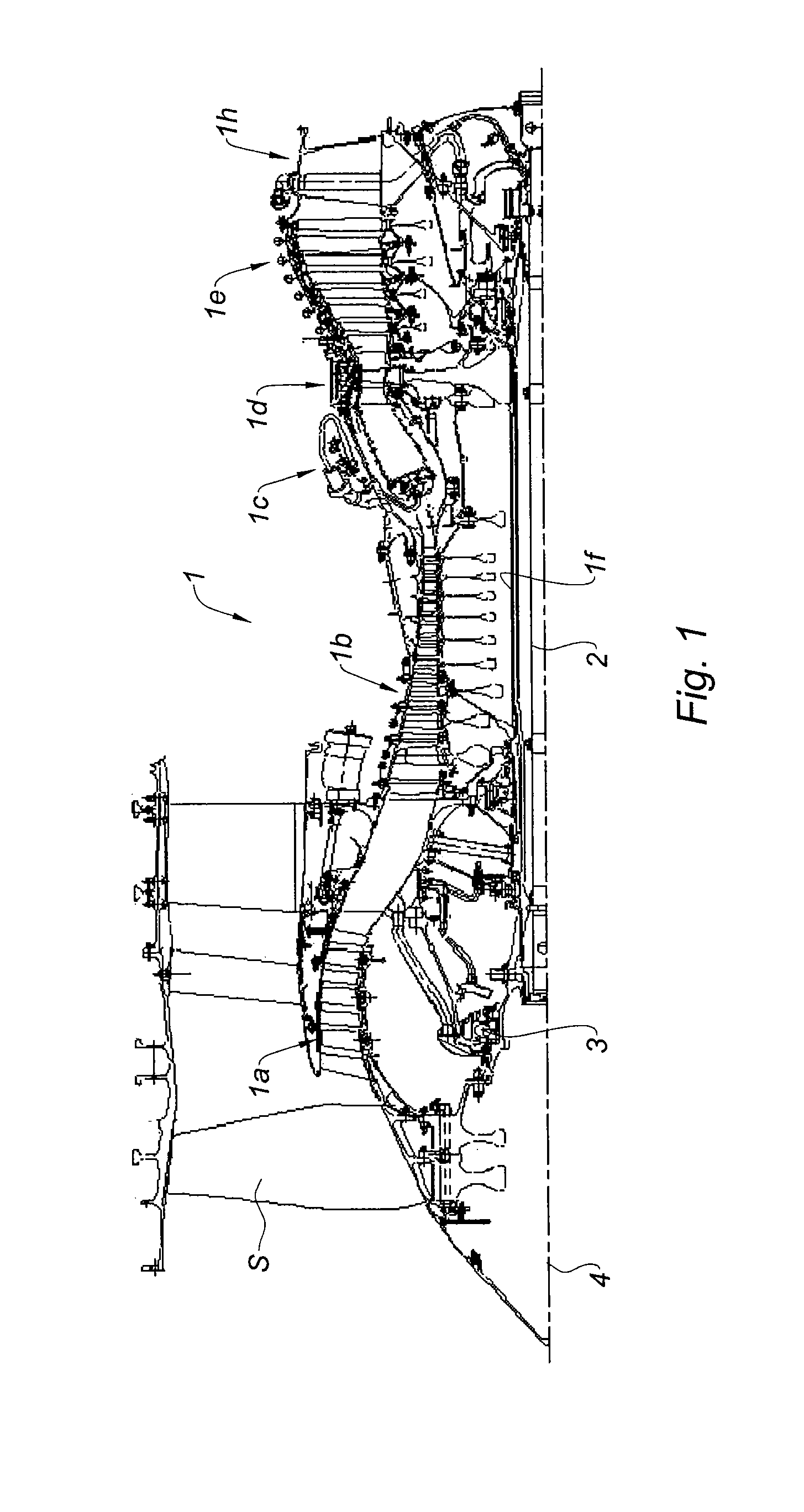
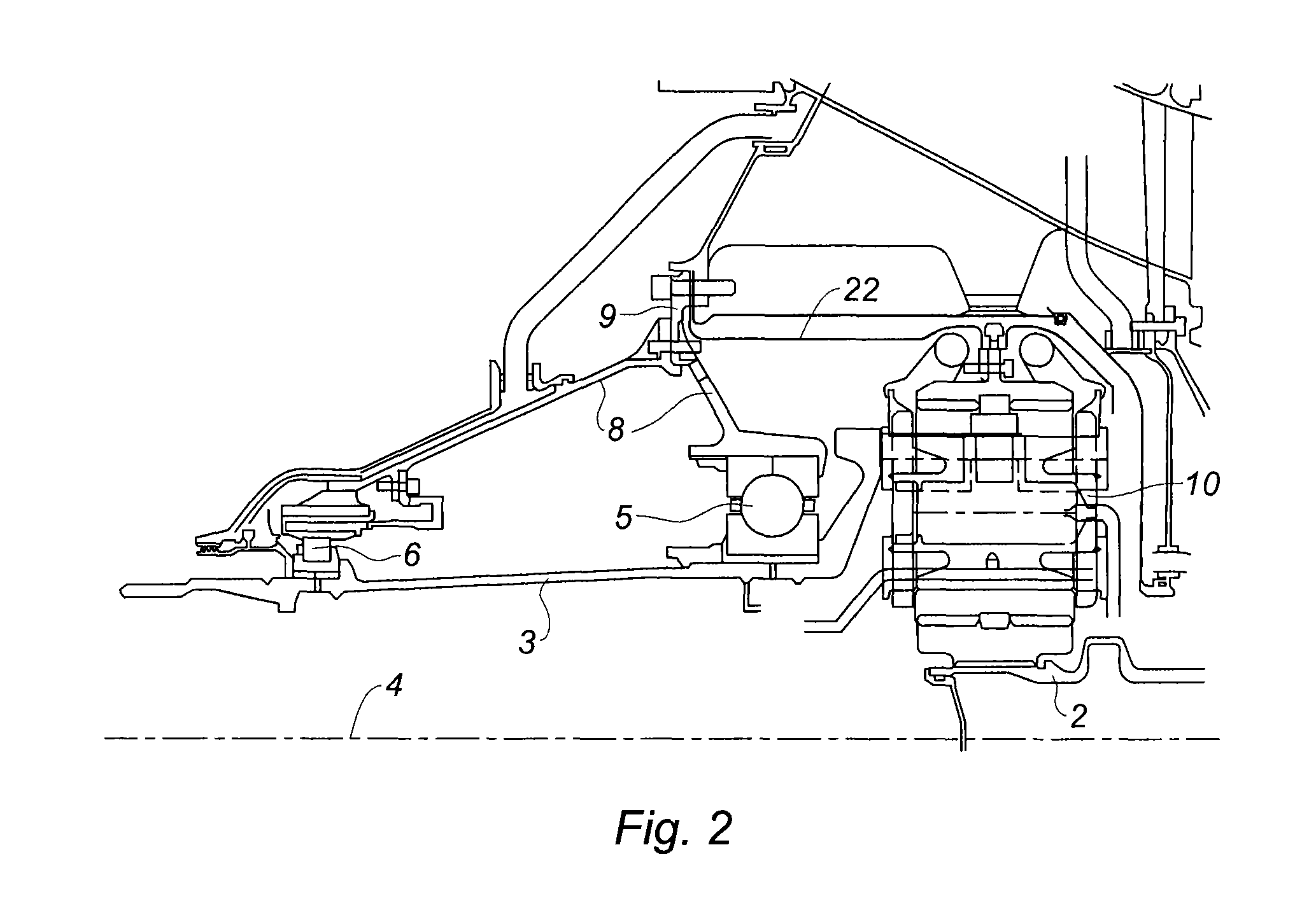
Reduction gear with epicyclic gear train having roller-bearing-mounted planet spindles

a technology of gear train and planet spindle, which is applied in the field of aeronautical propulsion, can solve the problems of pump size, weight and lifespan, and precautionary measures to be taken, and achieve the effects of reducing the number of gear train rollers

Active Publication Date: 2015-03-24
SN DETUDE & DE CONSTR DE MOTEURS DAVIATION S N E C M A
View PDF9 Cites 16 Cited by
  • Summary
  • Abstract
  • Description
  • Claims
  • Application Information

AI Technical Summary

Benefits of technology

[0006]It is an aim of the present invention to provide solutions to these drawbacks by proposing a reduction gear which has journal bearings between the planet gears and their spindles, remains operational and, in particular, does not require a specific lubrication circuit in the event of a breakdown.
[0008]The fact that the planet spindles are allowed to rotate freely makes it possible to compensate for seizure of the bearings of the planet gears and to continue to function if the planet gears can no longer rotate about their spindles.
[0009]Advantageously, the planet gear rotates about its planet spindle by means of a journal bearing and the planet spindle is mounted on the planet carrier via the intermediary of a rolling bearing. As the risk of the journal bearing seizing is relatively high, having a rolling bearing ensures the reliability of the degraded mode.
[0011]Advantageously, switching from one mode to the other is performed as a function of the temperature of the lubrication oil of said reduction gear. This thus provides for automatic switching from one mode to the other without the need for specific devices.
[0015]More preferably still, said flange plate comprises at its outer end at least one second face which extends in the radial direction facing a corresponding face positioned on said planet gear, the axial positioning of said end, produced by the oil at a temperature below the nominal operating temperature of the reduction gear, being designed so as to cause said two faces to press against each other. The adhesion produced by this pressure makes it possible to lock the rotation of the planet gear relative to its journal bearing. However, the planet gear spindle can rotate freely in the planet carrier.
[0016]It should be noted that, when the flange plate is pressed tightly against the first face of the planet carrier, it will be able to act as a torque limiter in the event of a breakdown. This is because if the journal bearing were to seize, for example as a consequence of a lubrication fault, the bearing would become locked in rotation and would transmit the torque from the planet gear to the flange plate. As the capacity for uptake of this torque is limited by the coefficient of adhesion between the flange plate and the planet carrier, the spindle will in fact be able to rotate freely in the planet carrier, and the reduction gear will not be locked, thus limiting the negative consequences of this seizure.

Problems solved by technology

They thus present difficulties in terms of operational reliability, and therefore require precautionary measures to be taken to prevent a breakdown such as degradation of the bearing or untimely in-flight engine shutdown.
The pump can also present problems in terms of size, weight and lifespan, especially because it is located at the heart of the engine and is therefore difficult to maintain.
Introducing this pump therefore presents the disadvantage of making the architecture of the engine more complex and goes against the desired aim of compactness and weight reduction.

Method used


Image

  • Reduction gear with epicyclic gear train having roller-bearing-mounted planet spindles
  • Reduction gear with epicyclic gear train having roller-bearing-mounted planet spindles
  • Reduction gear with epicyclic gear train having roller-bearing-mounted planet spindles

Examples


Embodiment Construction

[0040]The operation of a reduction gear with epicyclic gear train, as proposed by the invention, in which the planet spindles 16 are mounted on the planet carrier through a rotary bearing and are fitted with a locking flange plate made of a shape memory material, will now be described.

[0041]The reduction gear has two operating modes, depending on the position imparted to the flange plate 43 and depending on the element against which it is pressing. Switching from one mode of operation to the other is carried out automatically, as a function of the ambient temperature in the reduction gear and, in particular, the temperature of its lubrication oil.

[0042]In what is termed normal operation, which corresponds to the operation of reduction gears of the prior art, having a single mode of operation, or to reduction gears according to the invention in the configuration shown in FIGS. 4 and 5, the lubrication oil is hot and the flange plate 43 presses against the planet carrier 13. The flang...


PUM


Abstract

A reduction gear with epicyclic gear train including an annulus gear, and at least one planet gear rolling on the annulus gear and able to rotate about a planet spindle borne by a planet carrier is provided. The planet spindle is mounted such that it can itself rotate about its axis relative to the planet carrier. The reduction gear is suitable for mounting in a high bypass ratio jet engine for driving the fan thereof.

Description

BACKGROUND OF THE INVENTION[0001]The present invention relates to the field of aeronautical propulsion and, more particularly, to the field of high bypass ratio dual-flow jet engines, or turbofans.[0002]Modern turbomachines conventionally take the form of an assembly of modules which may comprise stationary and moving parts. A module is defined as a subassembly of a turbomachine having geometric features at the level of its interfaces with the adjacent modules, which features are sufficiently precise for the subassembly to be delivered individually, and having undergone an individual balancing when it comprises rotating parts. Assembling the modules makes it possible to build up a complete engine, by reducing as far as possible the operations of balancing and pairing the interfacing parts.[0003]Current turbofans comprise a plurality of compressor stages, in particular a low-pressure (LP) compressor and a high-pressure (HP) compressor which form part of the primary body of the engine...

Claims


Application Information

Patent Timeline
Patent Type & Authority Patents(United States)
IPC IPC(8): F16H47/08F02C3/107F02C7/36F02K3/06F16H3/44F16H57/08
CPCF02C7/36F02C3/107F16H57/082F16H3/44F02K3/06F16H2057/085F05D2260/4031Y02T50/671Y02T50/60F05D2260/34F05D2260/40311F16H57/0423
Inventor GALLET, FRANCOIS
Owner SN DETUDE & DE CONSTR DE MOTEURS DAVIATION S N E C M A
Why Eureka
Try Eureka