
Method and apparatus for determining the relative position of a target

a technology of relative position and target, applied in the direction of instruments, special-purpose vessels, and reradiation, can solve the problems of the location determined by an inertial navigation system may drift over time, and the inability to determine the location of the target, etc., to achieve less susceptible to jamming and hinder off-board communication.

Active Publication Date: 2015-03-24
THE BOEING CO
View PDF18 Cites 14 Cited by
  • Summary
  • Abstract
  • Description
  • Claims
  • Application Information

AI Technical Summary

Benefits of technology

The present disclosure provides a method, apparatus, and system that allows an aerial asset to accurately determine their current location and track a target, even when others try to jam or hinder communication. This is done by receiving information from sonobuoys and using it to determine the target's relative position to the navigation control vehicle. The system can then provide this information to the aerial asset to help them locate the target. This method is more reliable and less subject to drift compared to other positioning systems.

Problems solved by technology

In these instances, the aerial asset may be unable to determine its current location and, as a result, may be unable to determine the location of the target since the location of the target is generally determined relative to the location of the aerial asset.
While an inertial navigation system may not be susceptible to being jammed, the location determined by an inertial navigation system may drift over time.
As such, the location of an aerial asset as determined by an inertial navigation system may not be as accurate as desired, particularly in instances in which the inertial navigation system is utilized for a period of time such that the error attributable to drift accumulates.
Since an inertial navigation system may not determine the location of an aerial asset with sufficient precision, reliance upon an inertial navigation system, at least for extended periods of time, may also unable to locate and track a target in as precise a manner as is desired.

Method used


Image

  • Method and apparatus for determining the relative position of a target
  • Method and apparatus for determining the relative position of a target
  • Method and apparatus for determining the relative position of a target

Examples


Embodiment Construction

[0020]The present disclosure now will be described more fully hereinafter with reference to the accompanying drawings, in which some, but not all embodiments are shown. Indeed, this disclosure may be embodied in many different forms and should not be construed as limited to the embodiments set forth herein; rather, these embodiments are provided so that this disclosure will satisfy applicable legal requirements. Like numbers refer to like elements throughout.

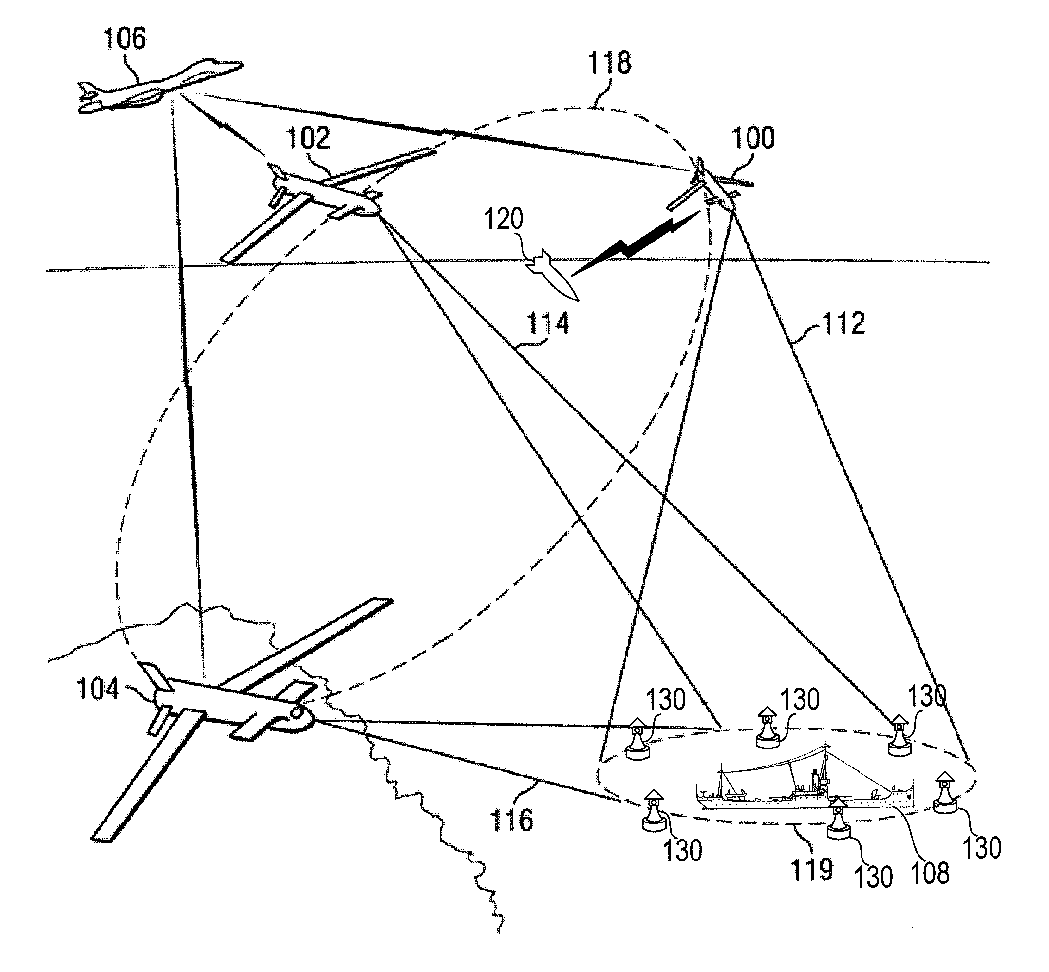
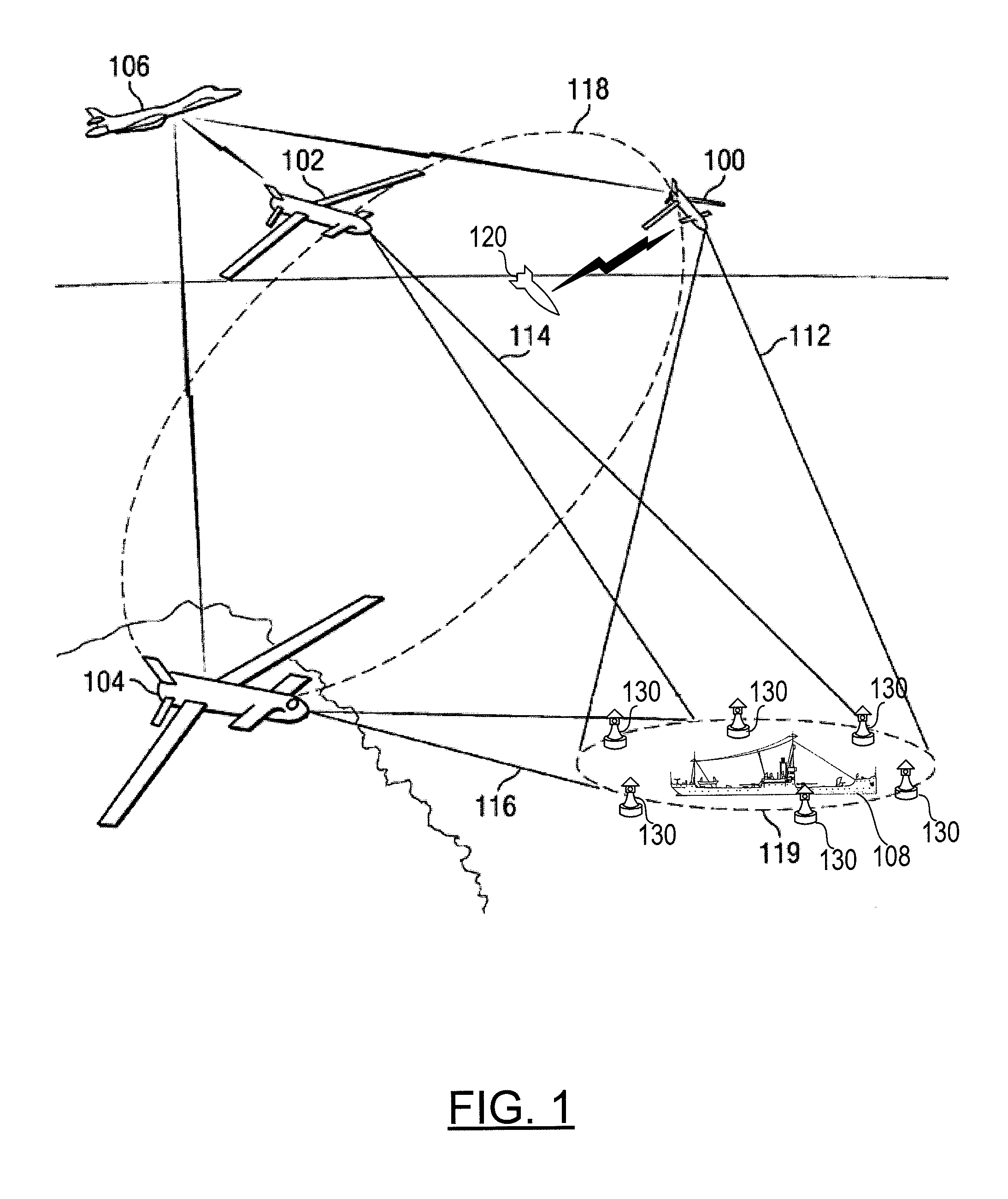
[0021]The method and apparatus of example embodiments may be utilized in a variety of systems in order to determine the relative position of a target, even in instances in the absolute position of the target cannot be determined, such as in instances in which the GPS or other positioning system is jammed. By way of example, FIG. 1 illustrates a system for determining the relative location of a target. The system of FIG. 1 illustrates a plurality of aerial assets (e.g., unmanned aerial vehicles (UAVs) 100, 102 and 104 and missile...


PUM


Abstract

A method, apparatus and system are provided to permit an aerial asset to determine its current location and to, in turn, locate and track a target even as efforts are made by others to jam or otherwise hinder offboard communications that may prevent reliance upon GPS or other positioning systems. A method includes receiving, at a navigation control vehicle, information regarding the relative position of a target with respect to each of the at least two sonobuoys. The method also determines a relative position of the target with respect to the navigation control vehicle at least partially based on the information regarding the relative position of the target with respect to each of the at least two sonobuoys. The method provides information regarding the relative position of the target to an aerial asset to facilitate location of the target by the aerial asset.

Description

TECHNOLOGICAL FIELD[0001]Embodiments of the present disclosure relate generally to the determination of the position of a target and, more particularly, to the determination of the relative position of the target with respect to one or more aerial vehicles.BACKGROUND[0002]Various types of aerial assets, including unmanned aerial vehicles (UAVs), missiles and the like, are employed to locate, track and intercept targets. For example, missiles of one form or another had been used in combat for centuries prior to the development of guided missile technology in the World War II era. Since then numerous technologies were developed in order to guide aerial assets to their targets or to otherwise locate a target. The use of some form of radiation (e.g., laser or radio waves) has been a common element in many of these guidance systems. However, as advancements in aerial guidance have improved, target sophistication continues to improve as well. The cost and complexity of each aerial asset, ...

Claims


Application Information

Patent Timeline
IPC IPC(8): G01S15/02G01S15/50B63B45/08B63B22/00G01S5/02
CPCG01S5/0284G01S5/0294G01S13/88F41G3/02F41G3/22F41G7/2206
Inventor LEONARD, JAMES V.
Owner THE BOEING CO
Learn More