
User-friendly welding helmet assembly

a welding helmet and user-friendly technology, applied in the field of welding helmet assemblies, can solve the problems of eye damage, possible blindness, difficulty in accessing the spatter shield, etc., and achieve the effect of easy attachment and detachmen

Active Publication Date: 2015-03-31
LINCOLN GLOBAL INC
View PDF94 Cites 36 Cited by
  • Summary
  • Abstract
  • Description
  • Claims
  • Application Information

AI Technical Summary

Benefits of technology

This patent describes a re-configurable welding helmet assembly for welders that allows for easy customization and replacement of parts. The assembly includes a common shell with a front open window and an interior lens that can be retained over the window with a retaining mechanism. The assembly also includes a front bezel that can be easily attached to the shell to align with the front window, and a spatter shield that can be easily replaced without needing to remove the lens. The assembly also includes an adjustable headgear that can be adjusted to centering the shell with respect to the headgear. The technical effects of this invention include customization options, easy replacement of parts, alignment with the front window, and improved spatter shield performance.

Problems solved by technology

The intense heat and brightness associated with welding can cause eye damage including, possibly, blindness.
Gaining access to the spatter shield is often difficult and time-consuming, requiring other elements (such as a filter) to be removed in order to remove the spatter shield.
Many times the spatter shield has to be removed from the interior of the helmet shell, which can be difficult, especially if the user (i.e., weldor) has large hands and fingers.
Being able to adjust the helmet to tilt at a proper angle with respect to the weldor's head and eyes is often difficult to accomplish.
Also, adjusting controls on an automatic darkening filter (ADF) shade cartridge, which is being used as the filter, may be difficult and time consuming, requiring various elements of the helmet to be dis-assembled to get at the controls, and then re-assembled once the controls are adjusted.
In general, many welding helmets today are not very user-friendly and require a user to spend a significant amount of time making adjustments and replacing various elements.

Method used


Image

  • User-friendly welding helmet assembly
  • User-friendly welding helmet assembly
  • User-friendly welding helmet assembly

Examples


first embodiment

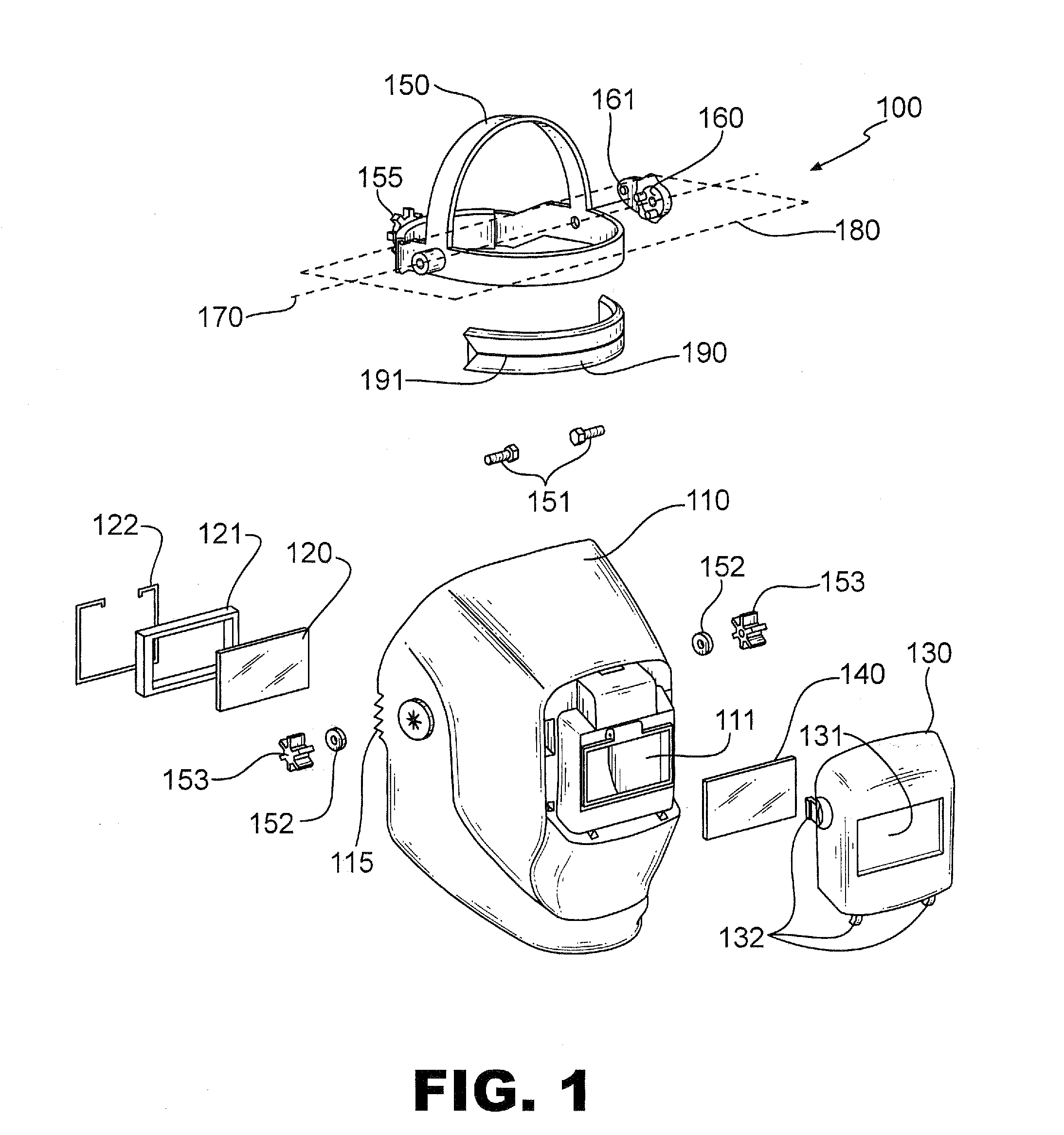
[0020]FIG. 1 is an exemplary illustration of an exploded view of a welding helmet assembly 100 corresponding to a first configuration using a common shell 110, in accordance with various aspects of the present invention. The common shell 110 may be used in several different welding helmet configurations, as will be described herein. A front portion of the shell 110 includes an open window 111 which defines a maximum viewing window for a weldor using the helmet assembly 100. The first open window 111 has dimensions of 2 inches by 4 inches, in accordance with an embodiment of the present invention. Other window dimensions are possible as well such as, for example, a 90 mm×10 mm window size which is standard in Europe.

[0021]An interior lens comprising a fixed filter lens 120 is adapted to cover the open window 111 at an interior front portion of the shell 110. The fixed filter lens 120 may be any type of fixed filter lens known in the art serving the purpose of protecting a weldor's ey...

second embodiment

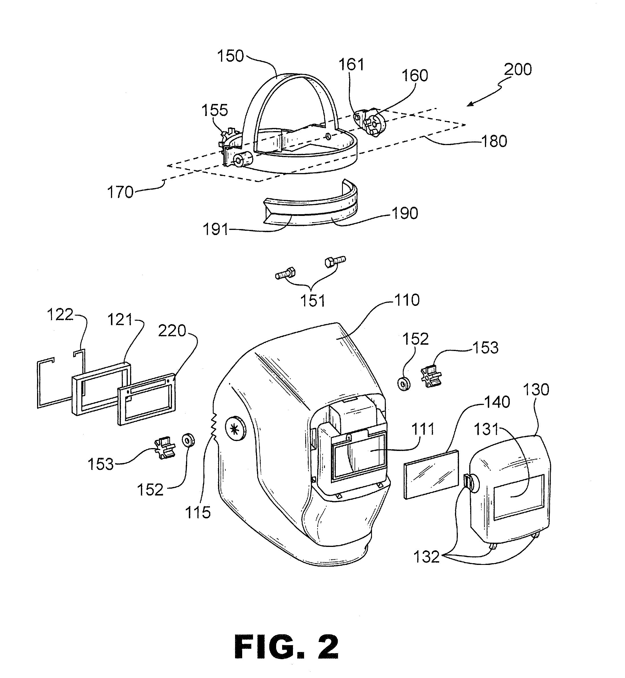
[0029]FIG. 2 is an exemplary illustration of an exploded view of a welding helmet assembly 200 corresponding to a second configuration using the common shell 110 of FIG. 1, in accordance with various aspects of the present invention. The welding helmet assembly 200 is the same as the welding helmet assembly 100 of FIG. 1 except that, instead of a fixed filter lens 120, the welding helmet assembly 200 includes an auto darkening filter (ADF) shade cartridge 220. Such an ADF shade cartridge 220 functions to protect the eyes of a weldor, in a more sophisticated manner than a simple fixed filter lens, by automatically sensing incident light and enabling at least one dark state of the filter when the intensity of the incident light is high enough. Otherwise, the state of the filter is relatively clear. The ADF shade cartridge 220 may have several intermediate darkening states where the darkening state that is enabled depends on the sensed intensity of the incident light. The ADF shade car...

third embodiment

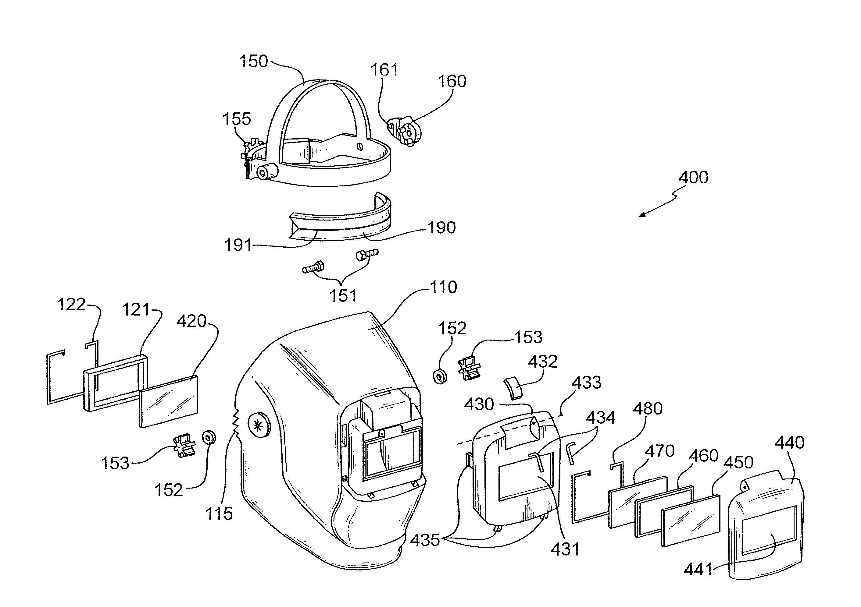
[0031]FIG. 4 is an exemplary illustration of an exploded view of a welding helmet assembly 400 corresponding to a third configuration using the common shell 110 of FIG. 1, in accordance with various aspects of the present invention. As described previously, a front portion of the shell 110 includes an open window 111 which defines a maximum viewing window for a weldor using the helmet assembly 400.

[0032]An interior lens comprising a clear plastic lens 420 is adapted to cover the open window 111 at an interior front portion of the shell 110. An interior retaining frame 121 is adapted to help retain the clear plastic lens 420 at the interior front portion of the shell 110 over the open window 111. A de-latchable interior retaining clip 122 is adapted to secure the clear plastic lens 420 and the interior retaining frame 121 in place at the interior front portion of the common shell 110 over the first open window 111. The interior retaining frame 121 and the interior retaining clip 122 ...


PUM


Abstract

User-friendly welding helmet assembly configurations to be worn on the head of a weldor are disclosed. The welding helmet assembly configurations include various advanced features including a spatter shield that is easily replaceable from an external front portion of a shell of the helmet assembly configuration, and an adjustable ratchet headgear within the shell having a repositionable lever adapted to easily adjust a detent position of the ratchet headgear with respect to the shell. Other user-friendly features are also provided, in accordance with various embodiments of the present invention.

Description

TECHNICAL FIELD[0001]Certain embodiments of the present invention relate to welding helmets. More particularly, certain embodiments of the present invention relate to re-configurable welding helmet assemblies with user-friendly features.BACKGROUND OF THE INVENTION[0002]A welding helmet is typically used during a welding process to help protect the weldor from various dangers such as sparks, heat, and flashes of light (e.g., visible light, ultraviolet light, and infrared light). A typical welding helmet covers the front and / or sides of the head of the weldor and includes a relatively transparent front portion to see through. The intense heat and brightness associated with welding can cause eye damage including, possibly, blindness. Therefore, a filter lens is typically used to filter out harmful light and heat.[0003]A spatter shield on the front of the welding helmet helps protect the weldor as well as the filter from flying sparks and other debris that may fly towards the helmet dur...

Claims


Application Information

Patent Timeline
Patent Type & Authority Patents(United States)
IPC IPC(8): A61F9/06A61F9/02F16P1/06
CPCA61F9/061A61F9/022F16P1/06A61F9/06
Inventor MATTHEWS, WILLIAM T.HARRIS, JAMES ALANLYNCH, III, JOSEPH DANIELMARIANO, DINO ANTHONYCOLBURN, ERIC R.ABY-EVA, GREGOIRE
Owner LINCOLN GLOBAL INC
Learn More