
Layshaft end bearing retrofit with external positive oil pressure delivery

a technology of positive oil pressure and end bearing, which is applied in the direction of bearing repair/replacement, bearing mounting/connection, bearing unit rigid support, etc., can solve the problems of catastrophic failure of the engine, bearing failure of horizontally opposing engines, and other modes of failure in such bearings, so as to increase the reliability of the bearing end support, increase the load carrying capacity, and improve the effect of the upgrade or repair path

Active Publication Date: 2015-03-31
IMS SOLUTION
View PDF50 Cites 6 Cited by
  • Summary
  • Abstract
  • Description
  • Claims
  • Application Information

AI Technical Summary

Benefits of technology

The patent is about improving the reliability and load carrying capacity of a bearing that receives external lubrication. It provides a way to retrofit or repair the bearing and lubrication system in engines. This upgrade or repair path is useful for mechanics and engine builders.

Problems solved by technology

Some horizontally-opposed engines are subject to bearing failure due to the use of a ball-bearing that supports the end of an intermediate layshaft used to couple the valve camshafts to the drive shaft.
In one mode of failure, the ball bearing assembly fills with oil, causing failure of the lubrication retaining seals and the internal lubrication itself, releasing the balls from the ball bearings into the engine, causing catastrophic failure of the engine.
Other modes of failure may also be present in such bearings.
Updates that have been implemented replace the original ball bearing with other ball-bearing types, but have limited lifetimes due to poor lubrication availability at the end of the intermediate layshaft, inherent issues with the bearings and bearing materials, and / or various operating conditions of the engine itself that tend to increase bearing wear both in idle and at high speeds.

Method used


Image

  • Layshaft end bearing retrofit with external positive oil pressure delivery
  • Layshaft end bearing retrofit with external positive oil pressure delivery
  • Layshaft end bearing retrofit with external positive oil pressure delivery

Examples


Embodiment Construction

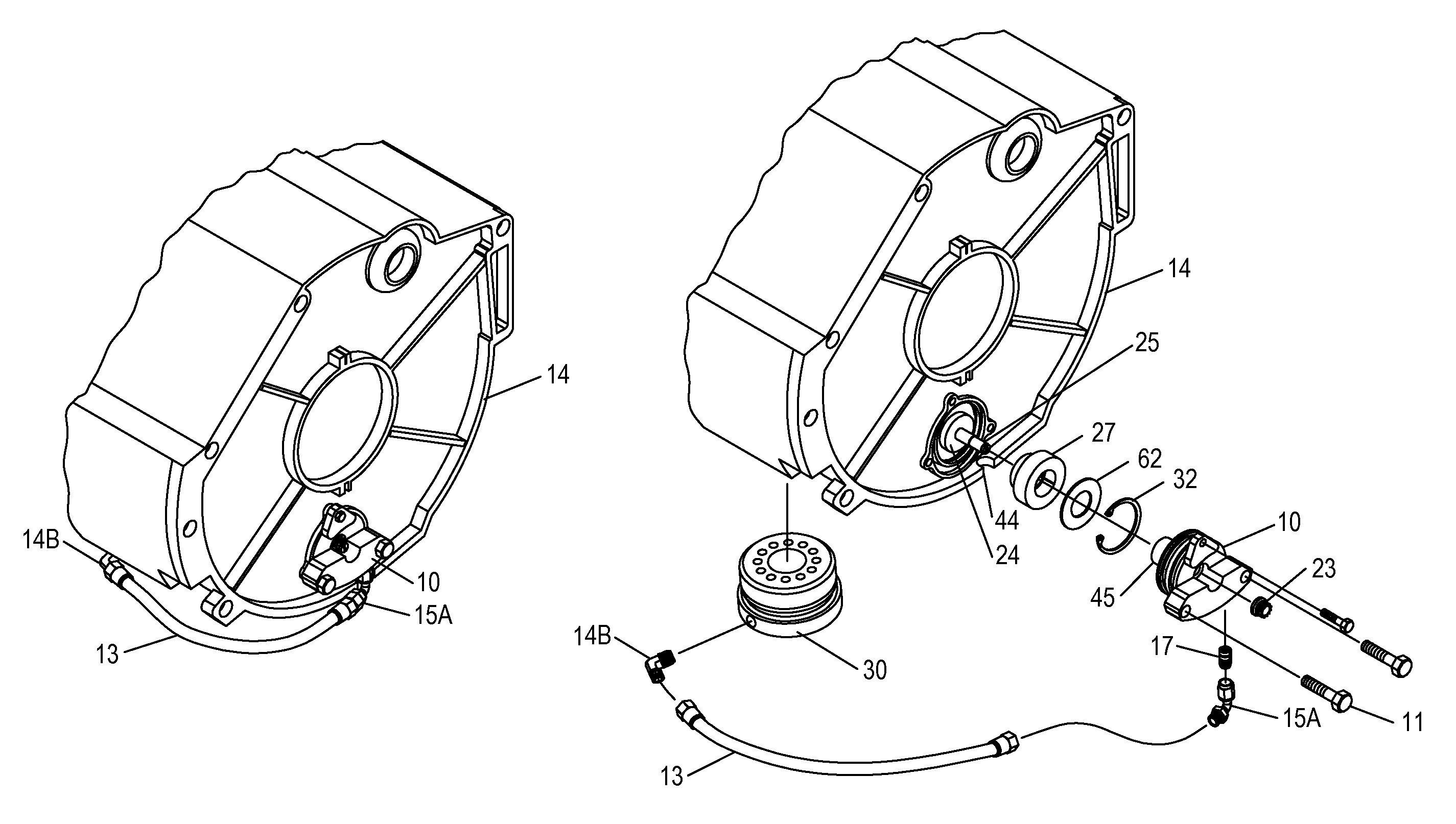
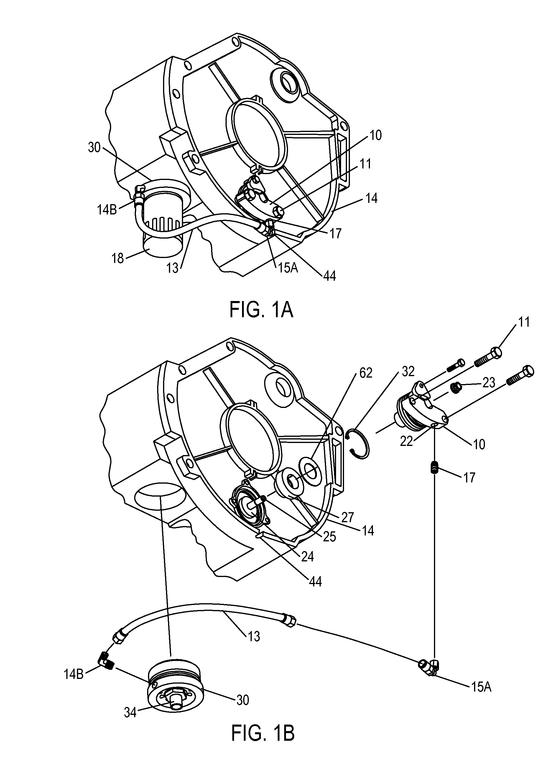
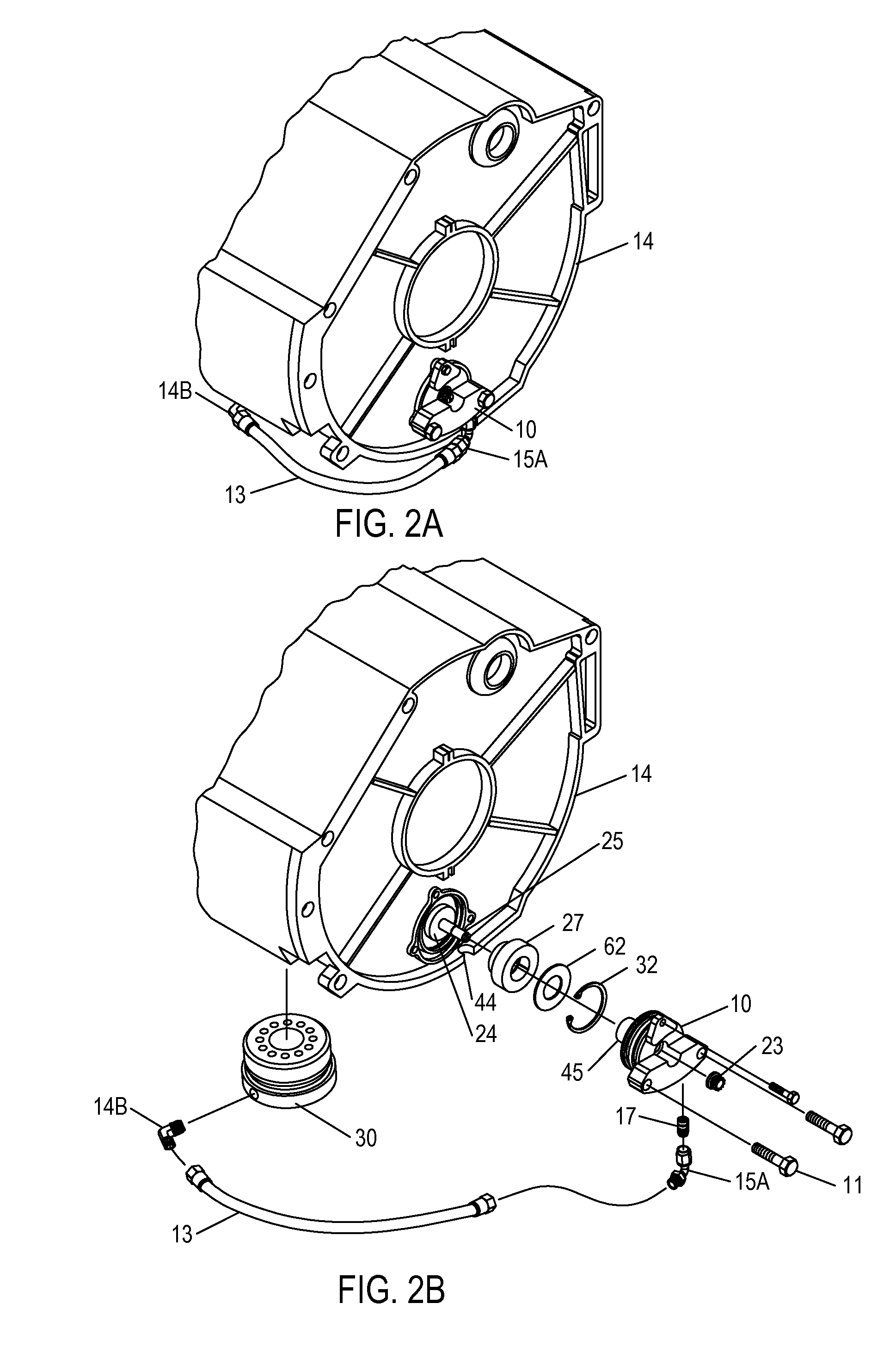
[0019]The present invention includes bearing assemblies that may be used in retrofitting and / or repairing engines subject to layshaft end-bearing failures, but having techniques that may also be used in new machine designs. In order to avoid the above-described failure mode of a ball-bearing assembly, the present invention incorporates a sleeve-type plain bearing that can be installed without disassembling the engine. A cap is provided with a post that extends through the bushing, and the stud on which the bushing rotates, so that the cap and bushing can be installed in the end of the intermediate shaft. The cap and bushing are captured within the intermediate shaft behind a snap ring, and then the stud, which is part of the bearing assembly mounting flange, is inserted within the sleeve as the mounting flange is installed and secured to the engine. Lubrication is provided through channels in the stud and mounting flange to the cap and bushing. The lubrication is provided to a port ...


PUM

PropertyMeasurementUnit
speedsaaaaaaaaaa
pressureaaaaaaaaaa
angleaaaaaaaaaa

Abstract

A bearing for retro-fit or repair of an engine provides high reliability through a sleeved bearing design having externally-supplied lubrication. The bearing assembly may be supplied as a kit including a lubrication delivery tube and an oil filter adapter having a port for supplying the external lubrication to a mounting flange of the bearing. In order to install the bearing a captive sleeve is inserted in a hollow end of the shaft being supported. A cap having a threaded stud is inserted with the sleeve into the hollow end of the shaft and secured by the required snap ring. Then a nut is used to secure the cap and the sleeve to a stud affixed to the mounting flange that secures the bearing assembly to the engine.

Description

[0001]This U.S. Patent Application claims priority under 35 U.S.C. §119 to U.S. Provisional Patent Application Ser. No. 61 / 677,511 filed on Jul. 31, 2012.BACKGROUND OF THE INVENTION[0002]1. Field of the Invention[0003]The present invention relates generally to end bearings for machines, and more specifically, to a high-reliability bearing retrofit for supporting rotation of an internal combustion engine layshaft, also referred to as an intermediate shaft.[0004]2. Description of the Related Art[0005]Some horizontally-opposed engines are subject to bearing failure due to the use of a ball-bearing that supports the end of an intermediate layshaft used to couple the valve camshafts to the drive shaft. In one mode of failure, the ball bearing assembly fills with oil, causing failure of the lubrication retaining seals and the internal lubrication itself, releasing the balls from the ball bearings into the engine, causing catastrophic failure of the engine. Other modes of failure may also ...

Claims


Application Information

Patent Timeline
Patent Type & Authority Patents(United States)
IPC IPC(8): F16C33/10B23P15/00F16C17/08
CPCF16C17/08B23P15/003F16C33/1045F16C2360/22F16C2237/00Y10T29/49638Y10T29/49231F01M7/00F01M11/03F16C33/04F16C35/02
Inventor RABY, JACOB DEANNAVARRO, CHARLES LAUREN
Owner IMS SOLUTION
Learn More