
Fluidized bed reactor

a reactor and flue bed technology, applied in the direction of measurement apparatus components, measurement apparatus housings, combustion processes, etc., can solve the problems of difficult to arrange homogeneous feed of fuel and secondary air, construction difficulties, and increased boiler height and bottom width, so as to achieve a large boiler and high-efficiency

Active Publication Date: 2015-03-31
FOSTER WHEELER ENERGIA OY
View PDF20 Cites 0 Cited by
  • Summary
  • Abstract
  • Description
  • Claims
  • Application Information

AI Technical Summary

Benefits of technology

The solution improves the structural rigidity and heat transfer efficiency of fluidized bed reactors, enabling the construction of larger, high-efficiency boilers with more reliable operation and uniform evaporation across the furnace, particularly in the inner corners.

Problems solved by technology

As it is at least structurally disadvantageous to have a very long and narrow bottom of the furnace, the height of the boiler and the width of the boiler bottom also have to be increased in order to have enough evaporation surfaces on the side walls.
The increase of the height may significantly lead to constructional difficulties, and the increase of the width can make it difficult to arrange homogeneous feed of the fuel and secondary air.
It can be difficult to form sufficiently strong and rigid side walls extending from the bottom to the roof of a high furnace, as the side walls are considerably thin relative to their height.
It is especially challenging to realize a high-efficiency once-through fluidized bed boiler.
The increase of the cross-sectional area of the furnace makes it challenging to maintain uniform behavior of the fluidized bed.

Method used


Image

  • Fluidized bed reactor
  • Fluidized bed reactor
  • Fluidized bed reactor

Examples


Embodiment Construction

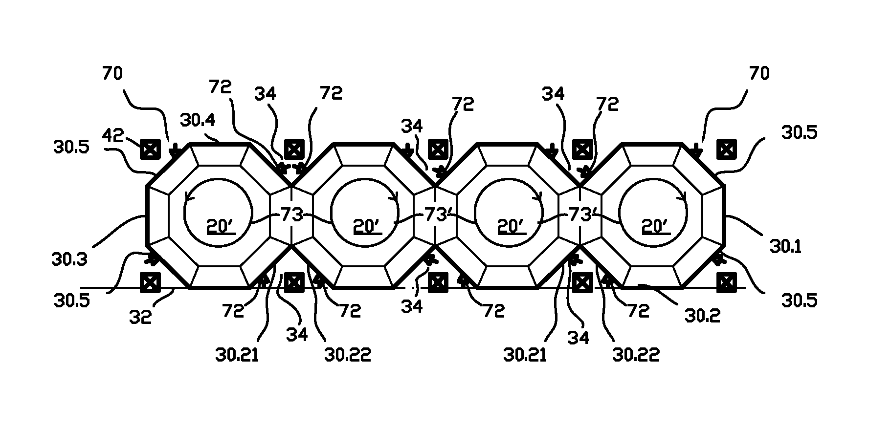
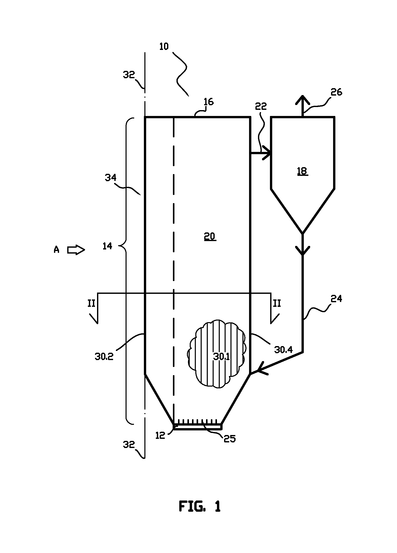
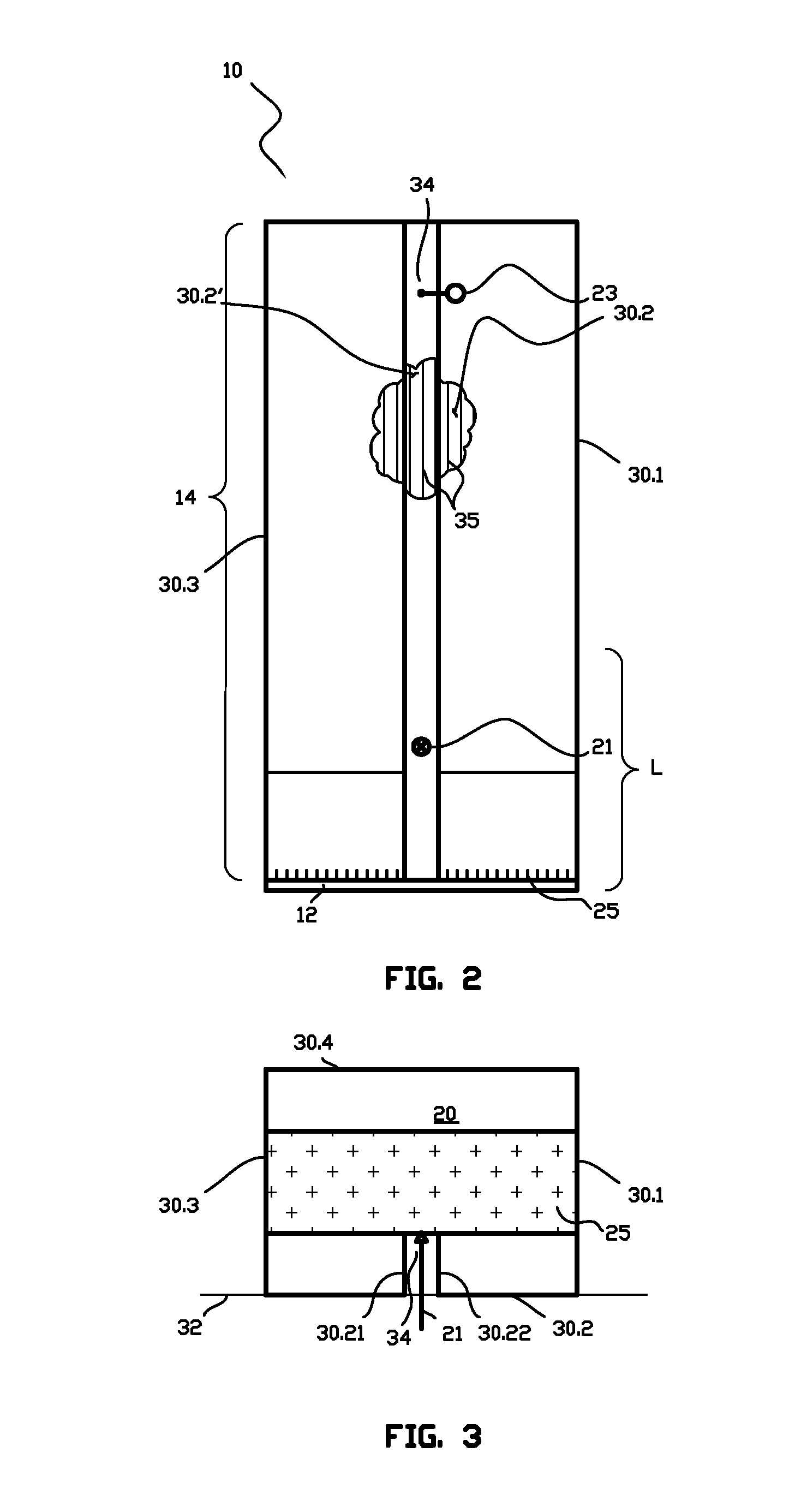
[0038]FIGS. 1, 2 and 3 schematically illustrate an embodiment of a fluidized bed reactor 10 in accordance with the invention, which, herein, is a circulating fluidized bed boiler. The circulating fluidized bed boiler 10 comprises a bottom portion 12, a roof portion 16 and side walls 14 extending vertically between the bottom portion 12 and the roof portion 16. The two opposing side walls 14 comprise an inclined lower portion. It is clear that the fluidized bed reactor 10 comprises numerous parts and elements that are not, for the sake of clarity, illustrated herein. FIG. 2 is a view of the fluidized bed reactor 10 of FIG. 1 in direction A and FIG. 3 illustrates a horizontal section II-II of the fluidized bed reactor 10 of FIG. 1. For the sake of clarity, FIGS. 2 and 3 do not show a solids separator, either.

[0039]The bottom portion 12, the roof portion 16 and the side walls 14 form a reaction chamber 20, which is a furnace, in a case that the reactor is a boiler. The bottom portion 1...


PUM


Abstract

A fluidized bed reactor includes a bottom portion, a roof portion, and side walls vertically extending between the bottom portion and the roof portion, forming a reaction chamber of the reactor. At least one side wall of the reaction chamber forms at least one vertical indentation in the reaction chamber, which indentation extends from the plane of the at least one side wall towards the reaction chamber. The indentation extending from the plane of the at least one side wall towards the reaction chamber is formed of a portion of the at least one side wall, protruding from the plane of the at least one side wall towards the reaction chamber, and the portion of the at least one side wall includes at least two substantially vertical indenting wall portions deviating from the plane of the at least one side wall at vertical lines within a distance from each other.

Description

[0001]This application is a U.S. national stage application of PCT International Application No. PCT / FI2010 / 050490, filed Jun. 11, 2010, published as International Publication No. WO 2010 / 142861 A2, and which claims priority from Finnish patent application number 20095674, filed Jun. 12, 2009.FIELD OF THE INVENTION[0002]The present invention relates to a fluidized bed reactor having a reaction chamber in which at least one side wall of the reaction chamber forms at least one indentation in the chamber, which indentation is substantially vertical and extends from the plane of the side wall towards the reaction chamber.BACKGROUND OF THE INVENTION[0003]The reaction chamber of a fluidized bed reactor typically comprises an inner portion having a rectangular horizontal cross section, defined by four side walls, a bottom portion and a roof portion, wherein solid material and bed material containing, for example, fuel, are fluidized by means of fluidizing gas introduced through the bottom,...

Claims


Application Information

Patent Timeline
Patent Type & Authority Patents(United States)
IPC IPC(8): B01J8/18B01J8/00F23C10/00F23C10/10F23C10/18
CPCB01J8/1836B01J8/0055F23C10/002F23C10/10F23C10/18B01J2208/00194F22B31/00B01J8/00B01J8/18F23C10/00
Inventor LANKINEN, PENTTIKINNUNEN, PERTTINEVALAINEN, TEEMU
Owner FOSTER WHEELER ENERGIA OY
Learn More