Pulse signal output circuit and shift register

a shift register and output circuit technology, applied in the direction of pulse technique, generating/distributing signals, instruments, etc., can solve the problem that the shift register might have an unstable operation, and achieve the effect of not easily changed over time, low power consumption, and long li

Inactive Publication Date: 2015-03-31
SEMICON ENERGY LAB CO LTD
View PDF165 Cites 1 Cited by
  • Summary
  • Abstract
  • Description
  • Claims
  • Application Information

AI Technical Summary

Benefits of technology

[0017]However, since the channel widths of the transistors 91 and 92 are already large, it is not preferable to further increase the channel widths in consideration of change over time and to increase the sizes of the transistors because these increases lead to an increase in power consumption. Further, to increase the channel widths and to increase the sizes of the transistors also lead to poor frequency characteristics. Further, the size of the driver circuit is increased; thus, a frame of a display device or the like is increased, which is a problem.
[0019]One object of one embodiment of the present invention is to provide a pulse signal output circuit with lower power consumption. Another object of one embodiment of the present invention is to provide a pulse signal output circuit whose characteristics are not easily changed over time and which has a longer lifetime. Another object of one embodiment of the present invention is to achieve at least one of the above-described objects.
[0036]According to one embodiment of the present invention, a pulse signal output circuit with lower power consumption can be provided. Further, a pulse signal output circuit whose characteristics are not easily changed over time and which has a longer lifetime can be provided.

Problems solved by technology

In the case where the shift register included in the driver circuit includes transistors having the same polarity, the shift register might have a problem of unstable operation, for example.

Method used


Image

  • Pulse signal output circuit and shift register
  • Pulse signal output circuit and shift register
  • Pulse signal output circuit and shift register

Examples


embodiment 1

[0063]In this embodiment, the configuration of a pulse signal output circuit of one embodiment of the present invention is described with reference to drawings.

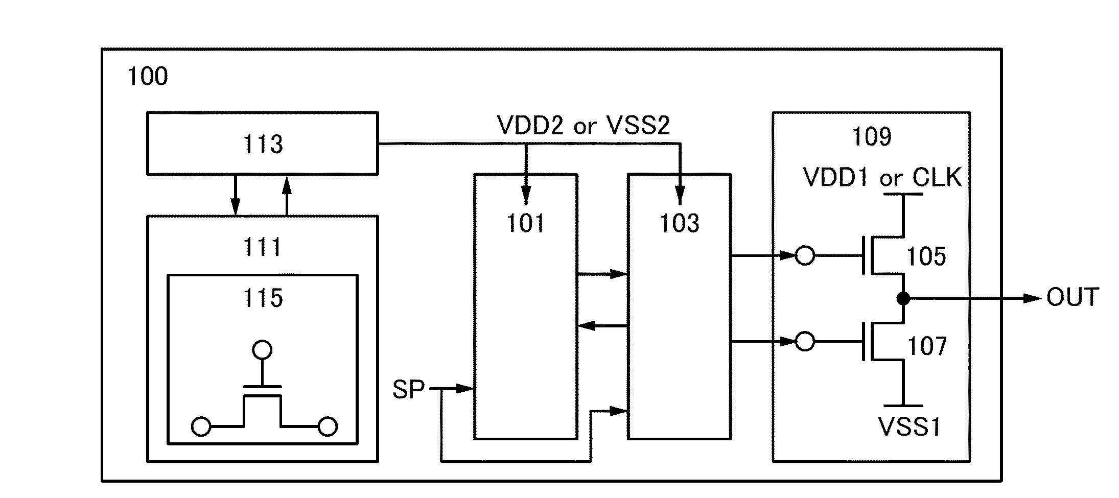
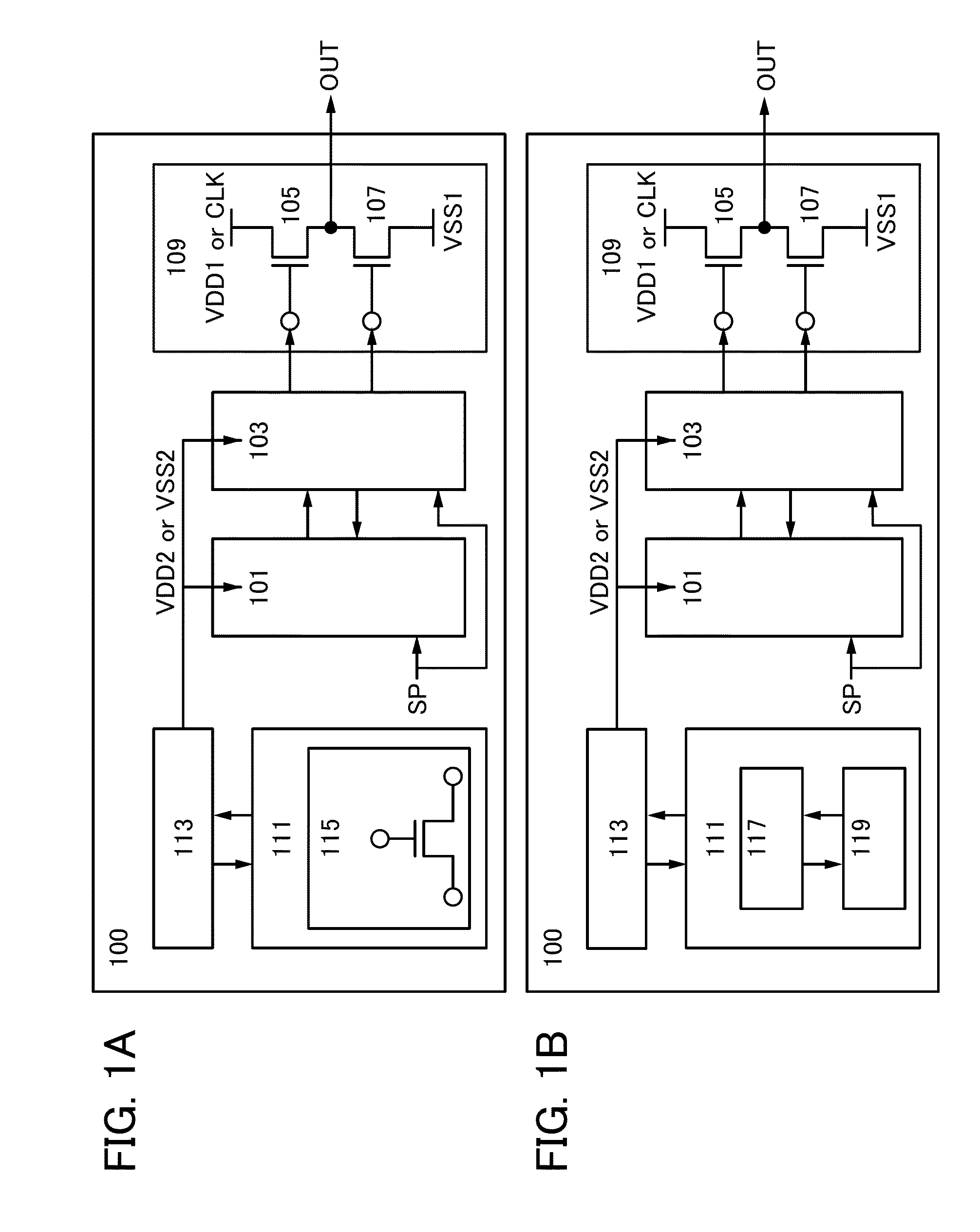
[0064]First, configuration examples of pulse signal output circuits of embodiments of the present invention are described. FIGS. 1A and 1B are each a block diagram of a pulse signal output circuit 100. The pulse signal output circuit 100 includes a first input signal generation circuit 101, a second input signal generation circuit 103, an output circuit 109 including at least a transistor 105 and a transistor 107, a reference circuit 111, and a power supply output circuit 113.

[0065]In the pulse signal output circuit 100 in FIG. 1A, the reference circuit 111 includes a reference transistor 115 which obtains the threshold voltages of the transistors 105 and 107. In the pulse signal output circuit 100 in FIG. 1B, the reference circuit 111 includes a counter 117 detecting the driving time of each of the transistors 105 and 107 an...

embodiment 2

[0074]In this embodiment, the configuration of a reference circuit included in a pulse signal output circuit of one embodiment of the present invention is described with reference to drawings. The pulse signal output circuit 100 is used as an example also in this embodiment.

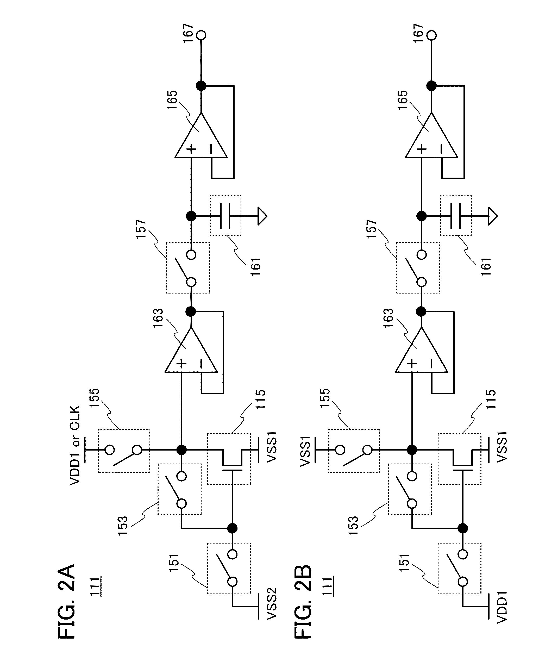
[0075]Configuration examples which can be used for the reference circuit 111 included in the pulse signal output circuit 100 are illustrated in FIGS. 2A and 2B. The reference circuits 111 illustrated in FIGS. 2A and 2B each include the reference transistor 115, a switch 151, a switch 153, a switch 155, a switch 157, a capacitor 161, a voltage follower 163, and a voltage follower 165. Note that the voltage follower 163 and the voltage follower 165 are not necessarily provided.

[0076]The reference circuit 111 illustrated in FIG. 2A is for obtaining the threshold voltage of the transistor 105 of the output circuit 109. The reference circuit 111 illustrated in FIG. 2B is for obtaining the threshold voltage of the tran...

embodiment 3

[0109]In this embodiment, specific configuration examples of a pulse signal output circuit of one embodiment of the present invention and a shift register including the pulse signal output circuit and the operation thereof are described with reference to drawings.

[0110]Configuration examples of a pulse signal output circuit and a shift register including the pulse signal output circuit of embodiments of the present invention are described with reference to drawings.

[0111]A shift register described in this embodiment includes first to n-th pulse signal output circuits 200—1 to 200—n (n≧2) and first to fourth signal lines 211 to 214 which transmit clock signals (see FIG. 4A). A first clock signal (CLK1) is supplied to the first signal line 211. A second clock signal (CLK2) is supplied to the second signal line 212. A third clock signal (CLK3) is supplied to the third signal line 213. A fourth clock signal (CLK4) is supplied to the fourth signal line 214.

[0112]In this embodiment, the f...


PUM


Abstract

To provide a pulse signal output circuit and a shift register which have lower power consumption, are not easily changed over time, and have a longer lifetime. A pulse signal output circuit includes a first input signal generation circuit; a second input signal generation circuit; an output circuit which includes a first transistor and a second transistor and outputs a pulse signal in response to a signal output from the first and second input signal generation circuits; a monitor circuit which obtains the threshold voltages of the first and second transistors; and a power supply output circuit which generates a power supply potential raised by a potential higher than or equal to a potential which is equal to or substantially equal to the threshold voltage and supplies the power supply potential to the first and second input signal generation circuits. A shift register includes the pulse signal output circuit.

Description

BACKGROUND OF THE INVENTION[0001]1. Field of the Invention[0002]One embodiment of the present invention relates to pulse signal output circuits and shift registers.[0003]2. Description of the Related Art[0004]Transistors which are used for most flat panel displays typified by liquid crystal display devices and light-emitting display devices include silicon semiconductors such as amorphous silicon, single crystal silicon, and polycrystalline silicon in many cases.[0005]Although transistors including amorphous silicon have low field effect mobility, they can be formed over larger glass substrates. In contrast, although transistors including polycrystalline silicon have high field effect mobility, they need a crystallization process such as laser annealing and cannot be always formed over larger glass substrates.[0006]In recent years, attention has been drawn to a technique in which, instead of a silicon semiconductor, a metal oxide exhibiting semiconductor characteristics is used for ...

Claims


Application Information

Patent Timeline
Patent Type & Authority Patents(United States)
IPC IPC(8): G11C19/00G11C19/18G11C19/28H03K3/353
CPCH03K3/353G11C19/184G11C19/28
Inventor MIYAKE, HIROYUKIOKAZAKI, KENICHIMIYAMOTO, TOSHIYUKINOMURA, MASAFUMIHAMOCHI, TAKASHIYAMAZAKI, SHUNPEI
Owner SEMICON ENERGY LAB CO LTD
Why Eureka
Try Eureka