Transmitter noise suppression in receiver

a transmitter and receiver technology, applied in the direction of amplitude demodulation, line-faulst/interference reduction, pulse technique, etc., can solve the problems of increasing the number of resonators, increasing the time needed to tune the transmit band filter, and still thermal noise and residual imd in the output of the transmitter. to achieve the effect of suppressing transmitter nois

Active Publication Date: 2015-03-31
TELEFON AB LM ERICSSON (PUBL)
View PDF34 Cites 24 Cited by
  • Summary
  • Abstract
  • Description
  • Claims
  • Application Information

AI Technical Summary

Benefits of technology

[0019]Systems and methods for suppressing transmitter noise in a receive band of a co-located receiver that are suitable for wideband applications are disclosed. Note, however, that while the systems and methods disclosed herein are suitable for wideband applications, the systems and methods disclosed herein are not limited thereto. In one embodiment, a system includes a transmitter, a main receiver, a secondary receiver, and a digital feedforward transmit noise cancellation subsystem. The transmitter is configured to upconvert and amplify a digital transmit signal to provide an analog radio frequency transmit signal at an output of the transmitter. The analog radio frequency transmit signal includes a desired signal in a transmit band of the transmitter and transmitter noise in a receive band of the main receiver. The main receiver is co

Problems solved by technology

However, even after linearization, there is still some thermal noise and residual IMD in the output of the transmitter.
The deep stop-band requirements of the transmit band filter result in several issues.
Specifically, the requirement for the transmit band filter to exhibit a deep stop-band increases the number of resonators needed for the transmit band filter and increases the time needed to tune the transmit band filter.
Further, increasing the number of resonators increases a size of the transmit band filter, increases an insertion loss of the transmit band filter, and makes the transmit band filter more costly to manufacture.
As such, the feedforward TX noise cancellation subsystem 32 is not suitable for wideband or multiband applications such as, for example, Long Term Evolution (LTE) cellular communications networks.
Phase shifters and vector modulators are limited in bandwidth and, as a result, limit the bandwidth of the feedforwar

Method used


Image

  • Transmitter noise suppression in receiver
  • Transmitter noise suppression in receiver
  • Transmitter noise suppression in receiver

Examples


second embodiment

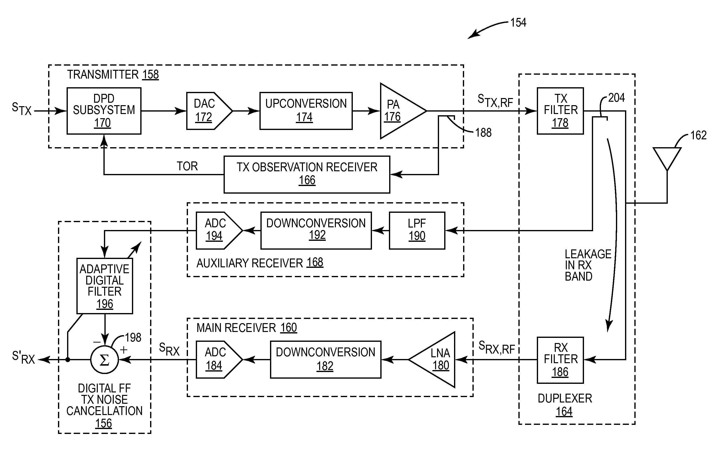
[0042]FIG. 5 illustrates a communication node 154 that includes a digital feedforward TX noise cancellation subsystem 156 that is suitable for wideband applications according to the present disclosure. This embodiment is similar to that of FIG. 4, but where the digital feedforward signal is generated separately from the feedback signal used to adaptively configure the digital predistortion. The communication node154 is any type of communication device or system such as, for example, a base station in a cellular communications network, a mobile terminal in a cellular communications network, or the like. The communication node 154 includes a transmitter 158 and a main receiver 160 coupled to an antenna 162 via a duplexer 164. The main receiver 160 is referred to herein as being co-located with the transmitter 158. In addition, the communication node 154 includes a TX observation receiver 166, an auxiliary receiver 168, and the digital feedforward TX noise cancellation subsystem 156 co...

third embodiment

[0051]FIG. 6 illustrates the communication node 154 that includes the digital feedforward TX noise cancellation subsystem 156 that is suitable for wideband applications according to the present disclosure. This embodiment is substantially the same as that of FIG. 5. However, in this embodiment, filtering is provided by transmit and receive filters 200 and 202. The transmit and receive filters 200 and 202 may be implemented as a duplexer. The transmit and receive filters 200 and 202 may be, for example, bandpass filters. The transmit filter 200 filters the signal from the coupler 188 to provide a filtered signal that corresponds to the desired signal in the transmit frequency band of the transmitter 158, which is then processed by the TX observation receiver 166. Likewise, the receive filter 202 filters the signal from the coupler 188 to provide a filtered signal that corresponds to the transmitter noise in the receive band, which is then processed by the auxiliary receiver 168.

fourth embodiment

[0052]FIG. 7 illustrates the communication node 154 that includes the digital feedforward TX noise cancellation subsystem 156 that is suitable for wideband applications according to the present disclosure. This embodiment is substantially the same as that of FIG. 5. However, in this embodiment, the input of the auxiliary receiver 168 is connected to a coupler 204 at an output of the transmit filter 178 of the duplexer 164. It should be noted that, in the same manner, the coupler 146 of FIG. 4 may be moved to the output of the transmit filter 132.


PUM


Abstract

Systems and methods for suppressing transmitter noise in a receive band of a co-located receiver that are suitable for wideband applications are disclosed. In one embodiment, an analog radio frequency transmit signal output by a transmitter includes a desired signal in a transmit band of the transmitter and transmitter noise in a receive band of a main receiver. A secondary receiver obtains a secondary receiver input signal that is representative of at least the transmitter noise in the receive band of the main receiver and outputs a digital feedforward signal. A digital feedforward transmit noise cancellation subsystem generates a digital transmitter noise cancellation signal that is representative of the transmitter noise in the receive band based on the digital feedforward signal and subtracts the digital transmitter noise cancellation signal from a digital receive signal output by the main receiver to thereby provide a compensated digital receive signal.

Description

FIELD OF THE DISCLOSURE[0001]The present disclosure relates to transmitter noise suppression in a receiver.BACKGROUND[0002]The output of a transmitter contains a desired transmit signal as well as Intermodulation Distortion (IMD) and thermal noise. The IMD is caused by non-linear behavior of components in the transmitter such as, for example, a power amplifier. Various linearization techniques (e.g., digital predistortion) are utilized to minimize IMD and, in some cases, thermal noise. However, even after linearization, there is still some thermal noise and residual IMD in the output of the transmitter. In the case of a frequency division duplex system, some of the thermal noise and the IMD exists in a paired receive band (i.e., in a receive band of a co-located receiver). In order to address this issue, currently, a transmit band filter at the output of the transmitter is specified to exhibit an adequately deep stop-band in the paired receive band. This deep stop-band reduces the a...

Claims


Application Information

Patent Timeline
IPC IPC(8): H04B1/38H04B1/62
CPCH04B1/62H04B1/525H04B1/123H04B15/00
Inventor WYVILLE, MARK
Owner TELEFON AB LM ERICSSON (PUBL)
Why Eureka
Try Eureka