Piston-cylinder assembly having integrated measuring device

a technology of measuring device and cylinder assembly, which is applied in the direction of mechanical equipment, engines without rotary main shafts, machines/engines, etc., can solve the problems of inability to use conventional systems, inability to maintain and calibrate the measuring device, and the spacing of the measuring device attached to the cylinder assembly from the outside, etc., to achieve convenient maintenance and calibration of the measuring device, facilitate the removal of the cover, and high accuracy and reproducibility

Active Publication Date: 2015-04-07
ZF CV SYST EURO BV
View PDF10 Cites 3 Cited by
  • Summary
  • Abstract
  • Description
  • Claims
  • Application Information

AI Technical Summary

Benefits of technology

[0012]According to yet another embodiment of the present invention, the PLCD sensor is integrated into a cylinder cover. In this way, the sensor, which is positioned fixedly relative to the cylinder cover, can be introduced into the housing of the piston-cylinder assembly with high accuracy and reproducibility. This is facilitated, in particular, by the fact that the cylinder cover is always mounted in the same arrangement on the housing. Dismantling of the sensor is possible by simple removal of the cover and facilitates the maintenance and calibration of the measuring device.
[0013]According to a further embodiment of a piston-cylinder assembly according to the present invention, the PLCD sensor is placed within a sleeve that is integrally formed on the cylinder cover. The sleeve can advantageously be produced with low tolerances and can be adapted to the sensor. Furthermore, exact positioning of the sleeve is possible if the latter is positioned relative to the cylinder cover by way of locating elements that are known to persons skilled in the art. In an approach of this type, the cylinder cover can be, for example, a simple cast part.
[0014]According to a further advantageous embodiment of the present invention, the PLCD sensor is integrated into the piston, and the ring magnet is integrated into the cylinder housing or into a seal. In this configuration, the measurement of the piston position does not take place as a result of a movement of a magnet connected fixedly to the piston relative to a sensor attached in a stationary manner, but rather as a result of a movement of the sensor relative to a ring magnet attached in a stationary manner. A design of this type can be advantageous for reasons of production economy or on account of special requirements from the user.

Problems solved by technology

This was not possible in conventional systems, since the spacing of a measuring device attached to the cylinder assembly from the outside from the movable piston and / or the piston rod was too great.

Method used


Image

  • Piston-cylinder assembly having integrated measuring device
  • Piston-cylinder assembly having integrated measuring device
  • Piston-cylinder assembly having integrated measuring device

Examples


Embodiment Construction

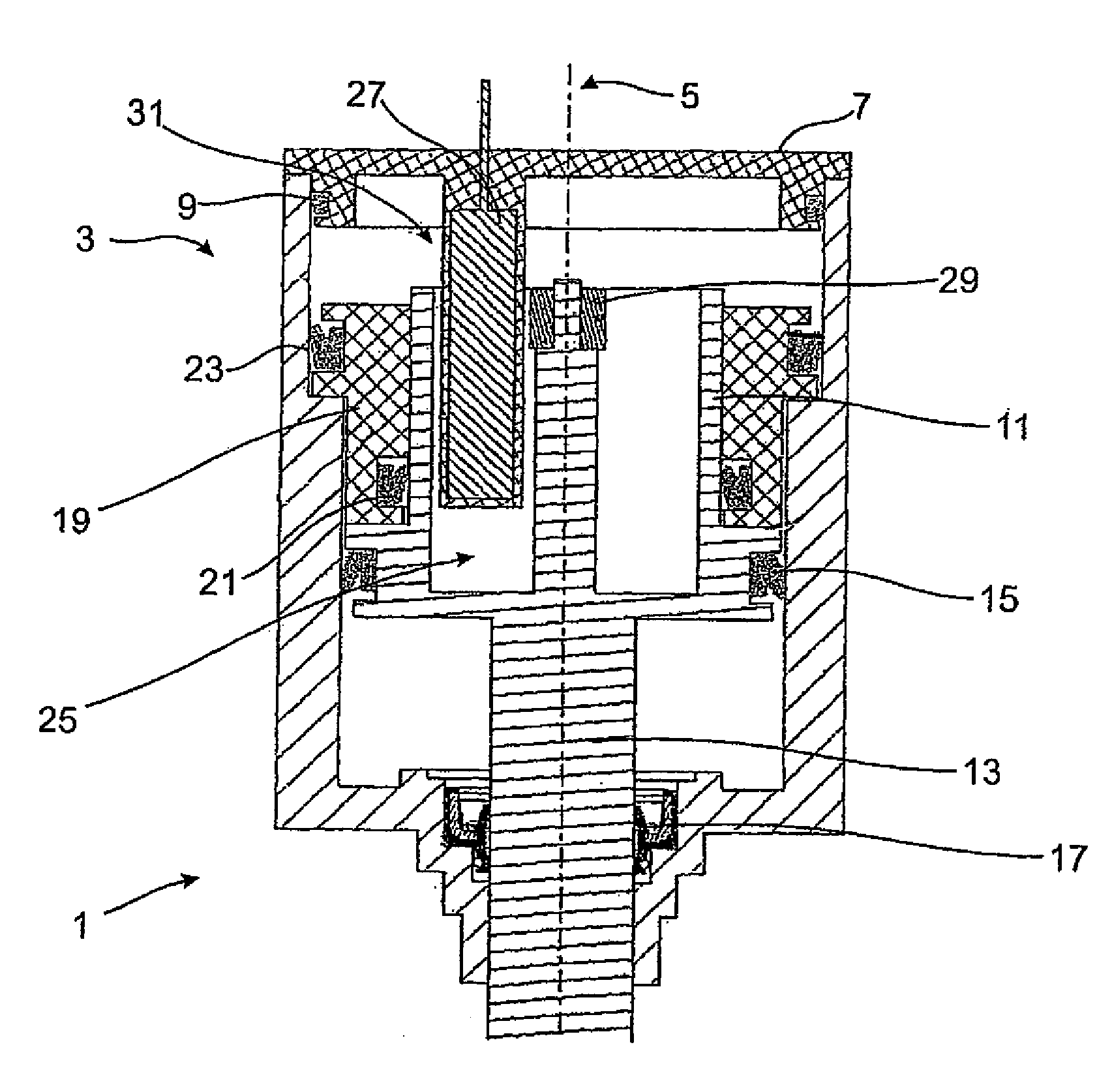
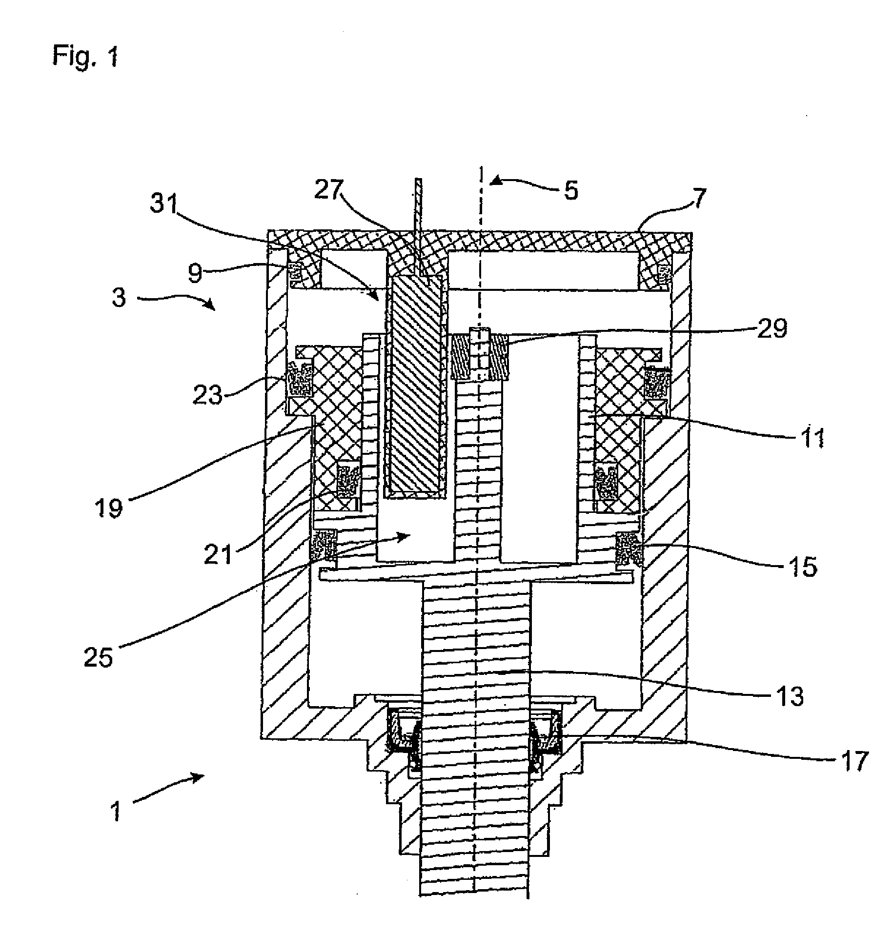
[0024]A piston-cylinder assembly 1 in accordance with an embodiment of the present invention is shown in FIG. 1. The piston-cylinder assembly 1 has a cylinder housing 3 that is closed with a cylinder cover 7. The cylinder housing 3 and the cylinder cover 7 are of rotationally symmetrical configuration with regard to an axis of symmetry 5 and are oriented coaxially with respect to one another. The cylinder cover 7 is sealed against an inner wall of the cylinder housing 3 by means of a sealing element 9. Evaluation electronics (not shown) can be arranged within the cylinder cover 7.

[0025]A main piston 11 is arranged within the cylinder housing 3 coaxially with respect to the axis 5. The main piston 11 is connected integrally to a piston rod 13, which is likewise oriented coaxially with respect to the axis 5. The main piston 13 is sealed by means of a sealing element 15 against an inner wall of the housing 3. A further sealing element 17 is arranged on an exit section of the housing 3,...


PUM


Abstract

A piston-cylinder assembly, in particular for pneumatic, hydraulic or mechatronic systems, includes a cylinder housing and a piston. The piston is coupled to a piston rod and disposed in the cylinder housing such that it can move along a longitudinal axis. A measuring device for detecting piston or piston rod position is provided inside the cylinder housing.

Description

FIELD OF THE INVENTION[0001]The present invention generally relates to a piston-cylinder assembly, in particular for pneumatic, hydraulic or mechatronic systems, having a cylinder housing and a piston, which is coupled to a piston rod, and which is arranged in the cylinder housing such that it can be moved along a longitudinal axis.BACKGROUND OF THE INVENTION[0002]Piston-cylinder assemblies of the general type under consideration are used predominantly in pneumatic gearshifts, mechatronic units, pneumatic systems and hydraulic systems. The piston-cylinder assembly usually serves the purpose of converting pressures that are applied to a piston into a movement of the piston rod. This movement is used in the different technical fields for controlling and / or for driving machines or machine elements.[0003]In order to make it possible to monitor and / or control the movement of such machines, it is of increased importance to be able to determine the piston stroke that actually takes place a...

Claims


Application Information

Patent Timeline
Patent Type & Authority Patents(United States)
IPC IPC(8): F15B15/28
CPCF15B15/2861F15B15/28
Inventor HEURICH, MIKEWIGGERS, TINO
Owner ZF CV SYST EURO BV
Why Eureka
Try Eureka