Gas generating system

a gas generator and gas technology, applied in the direction of transportation and packaging, pedestrian/occupant safety arrangements, vehicular safety arrangements, etc., can solve problems such as variable performance of gas generators, and achieve the effect of enhancing the performance of inflators

Inactive Publication Date: 2015-04-07
JOYSON SAFETY SYST ACQUISITION LLC
View PDF23 Cites 4 Cited by
  • Summary
  • Abstract
  • Description
  • Claims
  • Application Information

AI Technical Summary

Benefits of technology

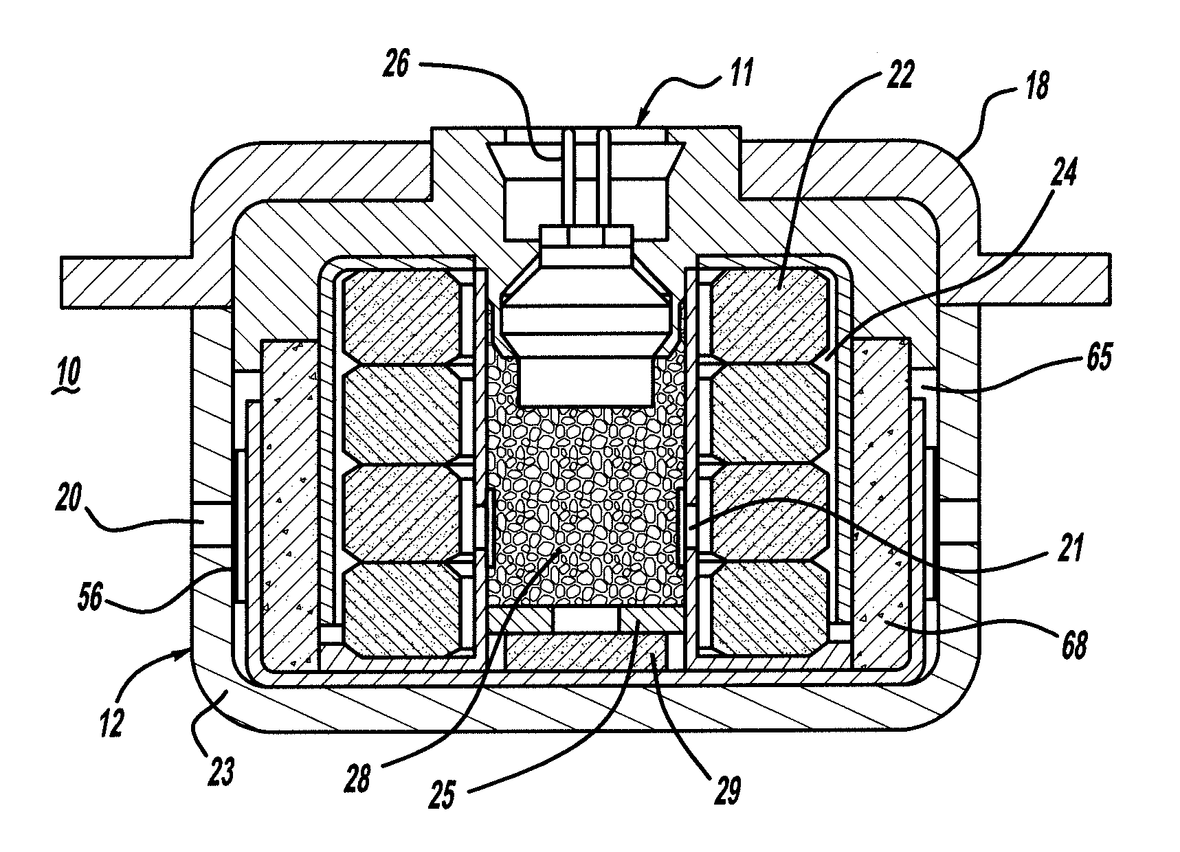
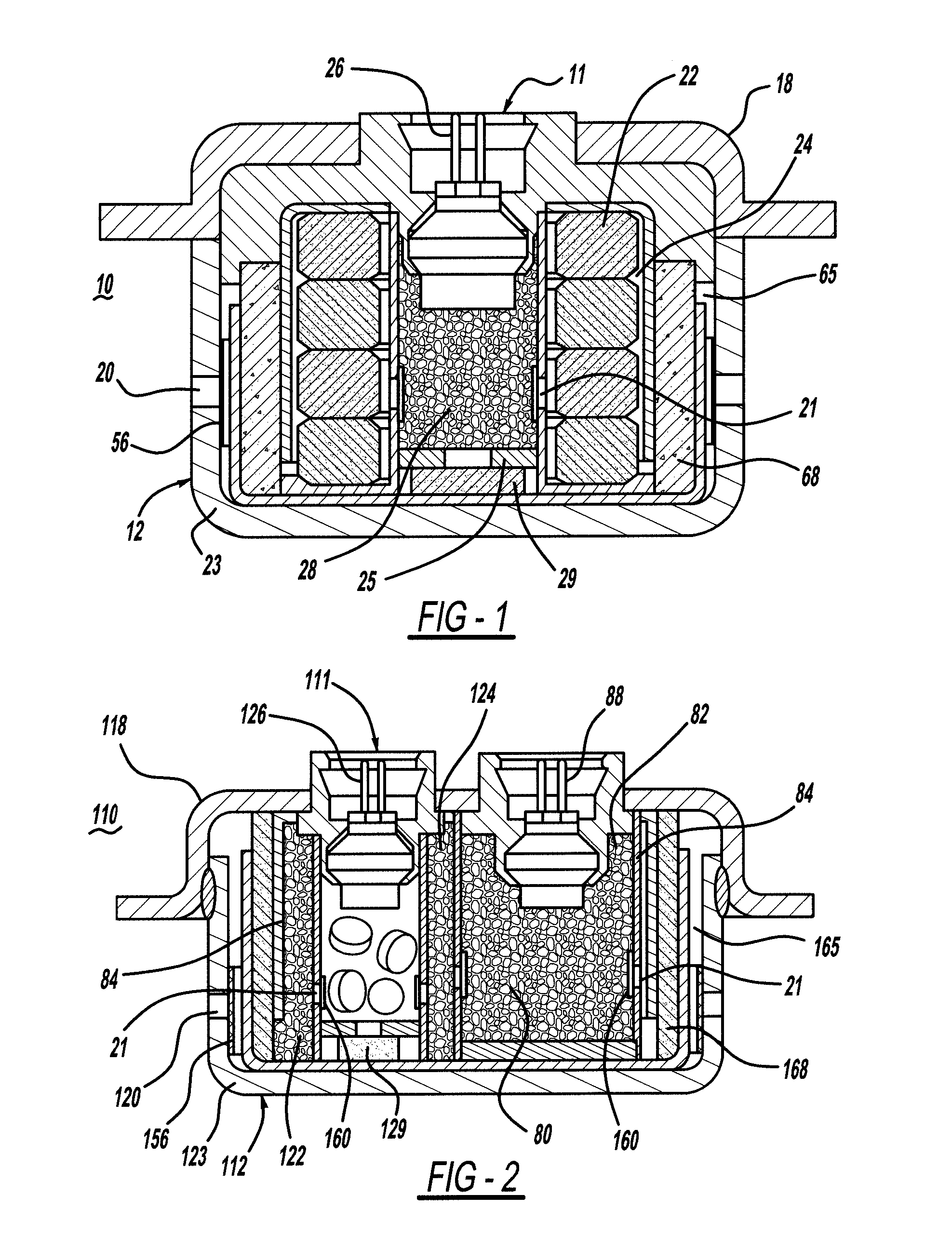
[0008]The above-referenced concerns are resolved by a gas generator containing an auto-ignition / booster composition within an auto-ignition / booster chamber, and a primary gas generant within a gas generant combustion chamber, wherein the inflator further contains a permeable separator between the auto-ignition / booster chamber and the primary gas generator. In accordance with the present invention, any potential off-gas products of the associated auto-ignition composition are able to migrate from the auto-ignition chamber to the primary gas generant / combustion chamber. As such, any off-gas products are sufficiently diluted or adsorbed within the overall internal environment of the inflator, thereby enhancing the performance of the inflator.

Problems solved by technology

Off-gassing, or the release of gases liberated by heat over time from various compositions within the gas generator, could occur and result in variability in the performance of the gas generator.

Method used


Image

  • Gas generating system
  • Gas generating system
  • Gas generating system

Examples


example 2

[0040]An inflator was manufactured in the same manner as Example 1. The same primary gas generant and the same MB compositions were employed. In contrast to Example 1, the combustion chamber and the MB chamber were perforated to permit vapor communication between the two chambers. The inflator was heat aged at 107 C for 408 hours. The inflator was also cycled between −40 C to 90 C, with a dwell time of 30 minutes between cycling from one extreme to the other, two hundred times. Eight trials were conducted in this manner. Upon activation of the inflator in each trial, the gases generated resulted in a satisfactory tank pressure over time (at 85 C in a 60 L tank), for each trial conducted.

example 3

[0041]An inflator was manufactured in the same manner as Example 1. The same primary gas generant and the same MB composition were employed. In contrast to Example 1, the combustion chamber and the MB chamber were perforated to permit vapor communication between the two chambers. In contrast to Example 2, these inflators also contained 13× zeolite as commercially available, in vapor communication with the contents of the AIB and primary gas generant chambers. The inflator was heat aged at 107 C for 408 hours. The inflator was also cycled between −40 C to 90 C, with a dwell time of 30 minutes between cycling from one extreme to the other, two hundred times. Eight trials were conducted in this manner. Upon activation of the inflator in each trial, the gas generated resulted in an optimum tank pressure over time, for each trial conducted. Although the curves defining tank pressure over time formed a tighter group (when evaluating the five trials taken together), as compared to Example ...


PUM


Abstract

A gas generator containing perforate internal chambers, each chamber in vapor communication with at least one other chamber in the gas generator, is provided. When granulated compositions are utilized in one or more of the chambers, permeable materials such as cheesecloth, neoprene, Tyvek™, metal or non-metallic screen, and other suitable fluid permeable materials, may be provided to physically seal the perforations of the various chambers, thereby separating the granulated composition(s) contained therein. In this way, off-gas products formed naturally over time may be effectively managed to ensure expected performance criteria of the associated inflator.

Description

CROSS-REFERENCE TO RELATED APPLICATIONS[0001]This application claims the benefit of U.S. Provisional Application Ser. No. 61 / 217,793 filed on Jun. 4, 2009.TECHNICAL FIELD[0002]The present invention relates to gas generators having an auto-ignition chamber / booster chamber, and a primary gas generating / combustion chamber. More particularly, the present invention relates to an improvement in the state of the art, whereby off-gas products formed within the gas generator over time are effectively re-mediated to ensure repeatability of performance.BACKGROUND OF THE INVENTION[0003]The present invention relates to gas generators in general, and more specifically, relates to inflators in vehicle occupant protection systems. Gas generators typically include a primary gas generant to produce sufficient amounts of gas to inflate an associated airbag and / or actuate an associated seatbelt pretensioner, for example.[0004]As an enhanced safety feature, gas generators may be provided with an auto-ig...

Claims


Application Information

Patent Timeline
Patent Type & Authority Patents(United States)
IPC IPC(8): B60R21/264
CPCB60R21/2644B60R2021/2648C06C9/00F42B3/04
Inventor RANSON, JUSTIN W.HORDOS, DEBORAH L.BURNS, SEAN P.
Owner JOYSON SAFETY SYST ACQUISITION LLC
Why Eureka
Try Eureka