Facial expression control device
a facial expression and control device technology, applied in dolls, toys, self-moving toy figures, etc., can solve the problems of high manufacturing cost of robot heads and complex fabrication processes, and achieve the effect of less actuators and complex fabrication processes
- Summary
- Abstract
- Description
- Claims
- Application Information
AI Technical Summary
Benefits of technology
Problems solved by technology
Method used
Image
Examples
first embodiment
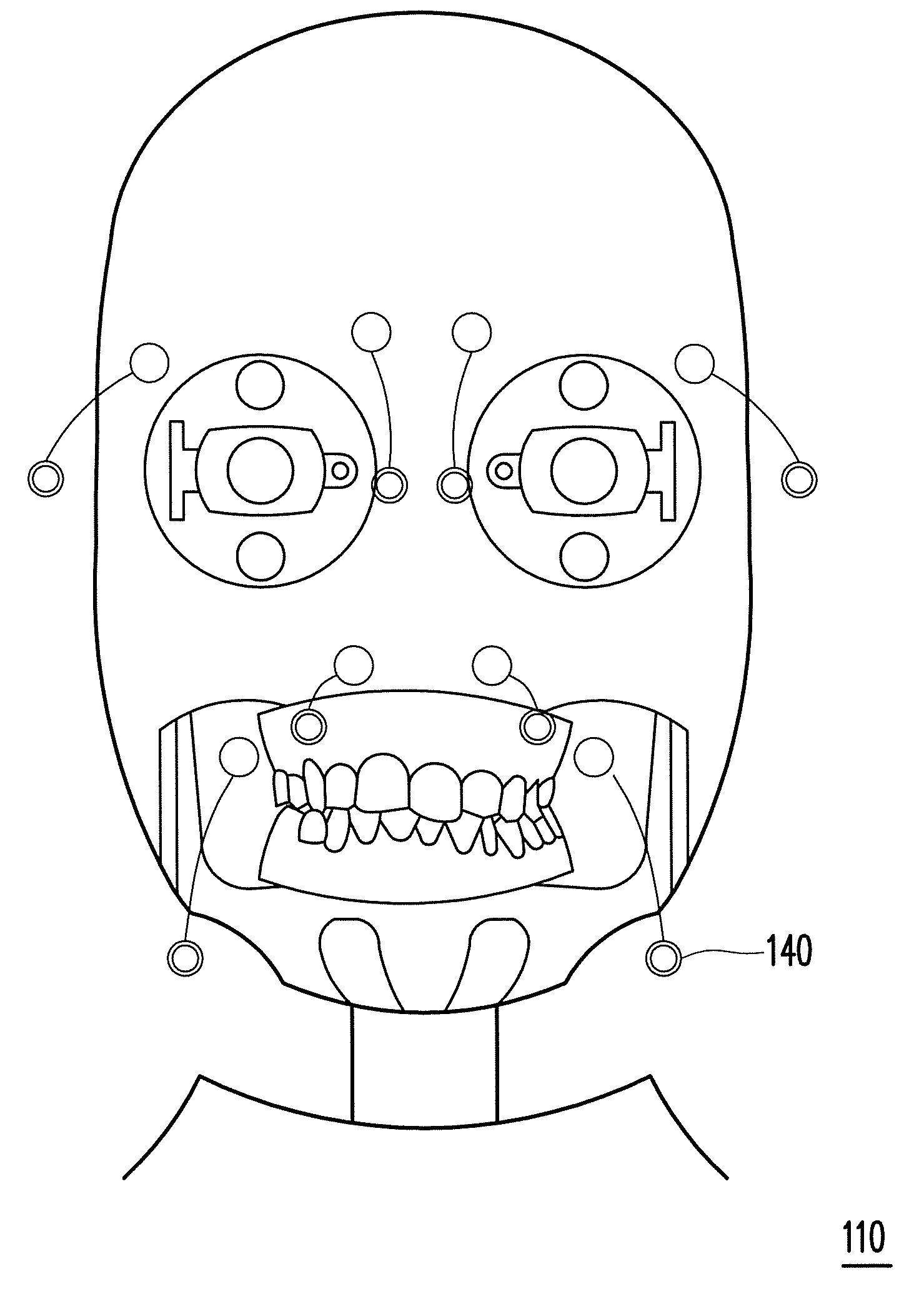
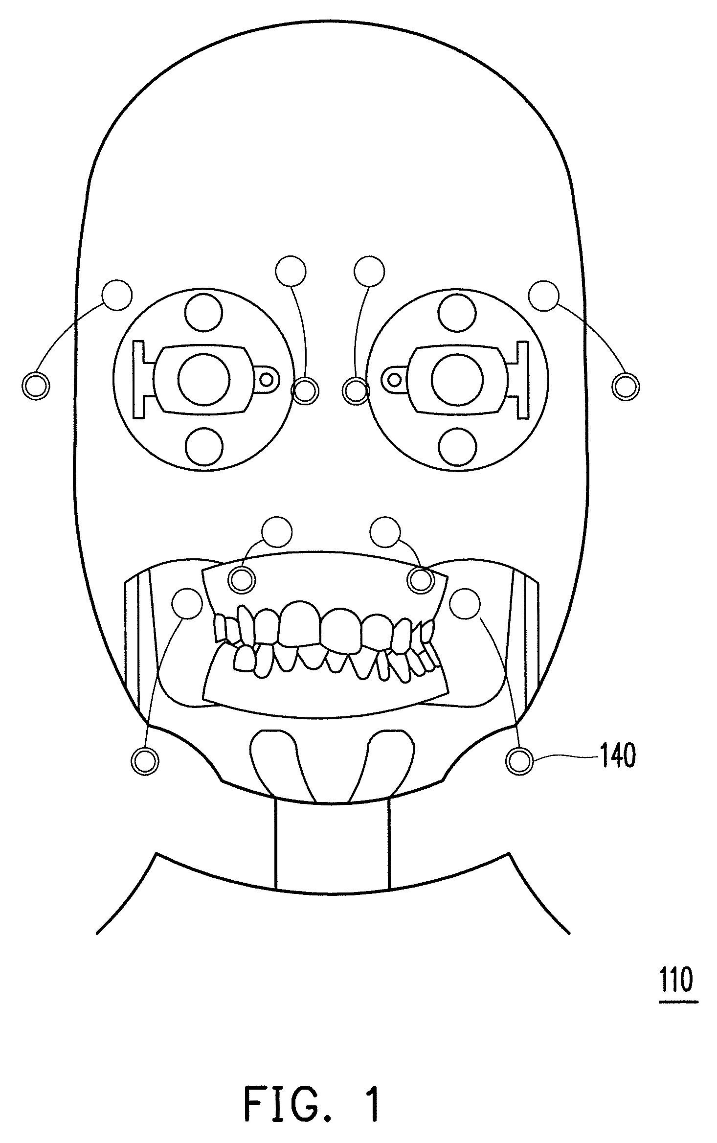
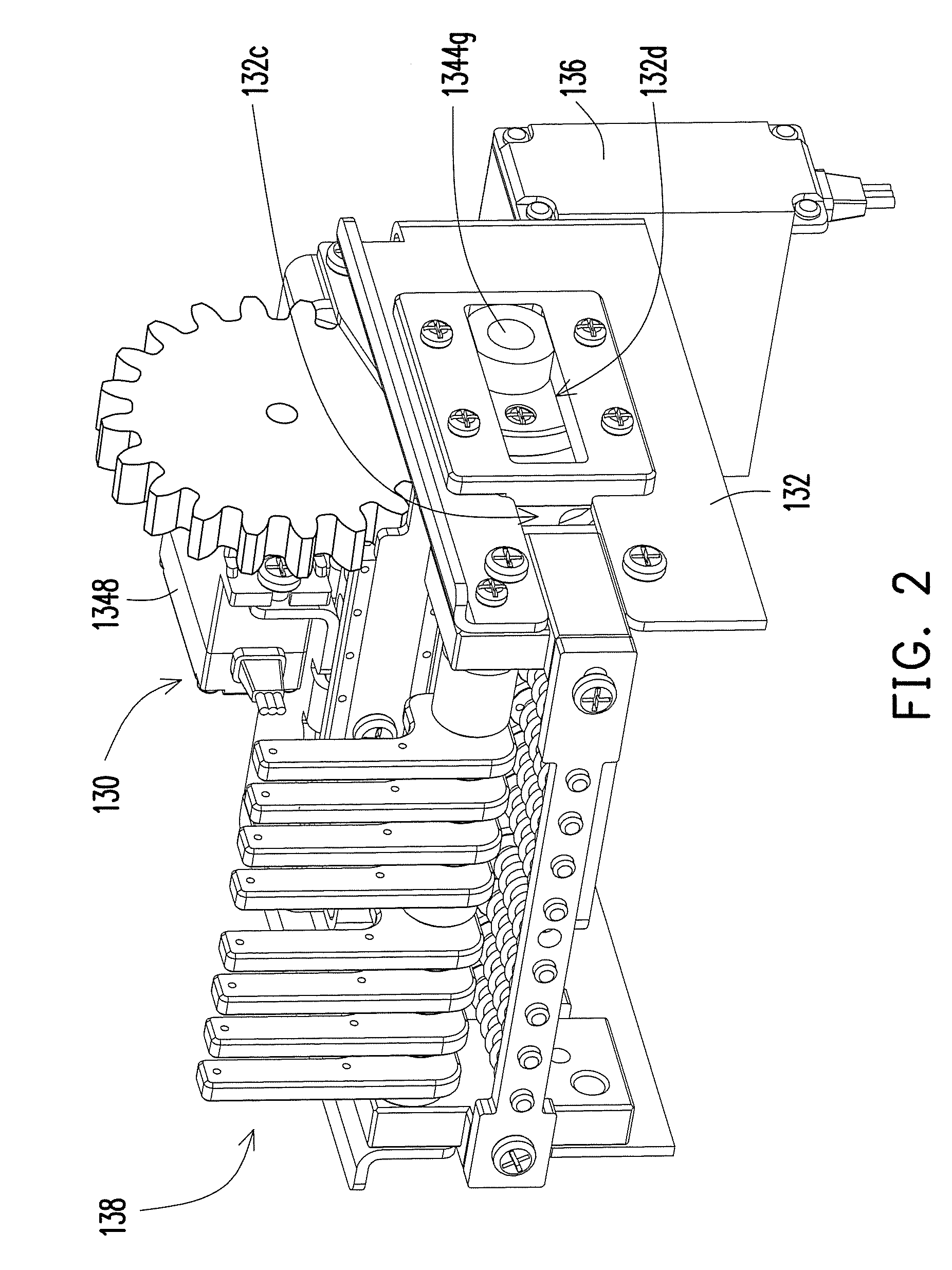
[0030]FIG. 1 is a schematic view of a facial skin of a robot head taken from the head of the robot. FIG. 2 is a schematic view of a facial expression control device disposed in the head. Referring to FIG. 1 and FIG. 2 together, the robot head includes a head 110, a facial skin (not shown), a facial expression control device 130, a main base 132 and a pushing assembly 136, wherein the head 110 has a cavity (not shown) used for placing the facial expression control device 130. The main base 132 is disposed in the cavity and the facial skin covers the head 110. The facial expression control device 130 is assembled to the main base 132 and connected with the facial skin. And the pushing assembly 136 is located relatively behind the head 110. The pushing assembly 136 pushes the facial expression control device 130 so as to pull the control points of the facial skin to make the robot head show facial expressions.
[0031]FIG. 3 is an exploded view of the facial expression control device of F...
second embodiment
[0047]FIG. 12 is a schematic view of the frame, the rotating element and the actuator of the second embodiment of the present invention. Referring to FIG. 3 and FIG. 12, though only one actuator 1348 is used to directly control one rotating element 1344 in the above mentioned embodiment, in order to increase the diversity of the facial expressions, one rotating element 2344 separated into two parts are used in this embodiment and other mechanical driving methods, for example, linkage, gear or combination thereof are used, so that one actuator 1348 can simultaneously drive the two rotating elements 2344, and the rotating directions of the two parts of the rotating element 2344 may be the same or opposite, and at the same time the rotating angles of the two parts of the rotating element 2344 can be the same or different. In this way, the facial expression control structures 2344b of the rotating elements 2344 can have much more combinations, and thus the robot head can have much more ...
third embodiment
[0048]In addition, though one row of the pushing bars and one row of the facial expression control structures are used in the description of the first embodiment, by this teaching people who have ordinary skill in the art may derive to other modifications according to the actual requirements. For instance, more rows of the pushing bars 1346 and more rows of the facial expression control structures 1344b can be disposed. FIG. 13 is a schematic view of the third embodiment of the present invention. Referring to FIG. 13, the rotating element 1344′ is a polyhedral prism. In FIG. 13, the included angle formed between any two adjacent edges 1344a′ and 1344a″ of the cross-sectional of the polyhedral prism are the same, and two rows of the facial expression structures 1344b′ can be disposed on each of the edges 1344a′ (or 1344a″). And the two pushing bars 1346 are respectively inserted into the two rows of the facial expression control structures 1344b′ of the rotating element 1344′. Corres...
PUM
 Abstract
Description
Claims
Application Information
 - R&D
- Intellectual Property
- Life Sciences
- Materials
- Tech Scout
- Unparalleled Data Quality
- Higher Quality Content
- 60% Fewer Hallucinations
Browse by: Latest US Patents, China's latest patents, Technical Efficacy Thesaurus, Application Domain, Technology Topic, Popular Technical Reports.
© 2025 PatSnap. All rights reserved.Legal|Privacy policy|Modern Slavery Act Transparency Statement|Sitemap|About US| Contact US: help@patsnap.com


