Traffic light driving control circuit
a control circuit and traffic light technology, applied in the field of driving integrated circuits, can solve the problems of increasing cost, difficulty in managing circuit elements, and only executing certain detections and controls by itself, and achieve the effects of less circuit elements, reduced element cost, and simplified managemen
- Summary
- Abstract
- Description
- Claims
- Application Information
AI Technical Summary
Benefits of technology
Problems solved by technology
Method used
Image
Examples
first embodiment
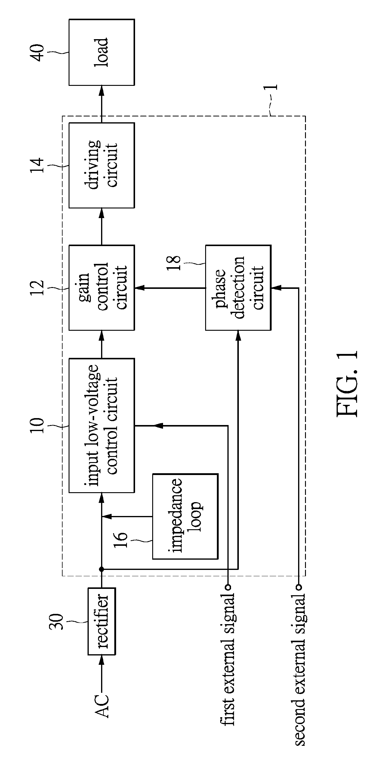
[0016]Referring to FIG. 1, FIG. 1 shows a block diagram of a drive IC for controlling a traffic light of the instant disclosure. As shown in FIG. 1, an input end of the drive IC 1 for controlling a traffic light is connected to a rectifier 30. The rectifier 30 receives and rectifies an AC power source and transmits the rectified current to the drive IC 1. An output end of the drive IC 1 is connected to a load 40, and the load 40 will be driven by the drive IC 1. The load 40 can be an LED illumination module, an LED light string, many lamp sets that are in serial, an LED lamp module or the like, but it is not limited herein. The rectifier 30 can be a full-bridge rectifier, a half-bridge rectifier, a center-tapped full-bridge rectifier or the like, but it is also not limited herein. Moreover, the AC power source can be a utility power. The drive integrated circuit having circuits having different functions for driving or controlling traffic lights which are all integrated in one singl...
second embodiment
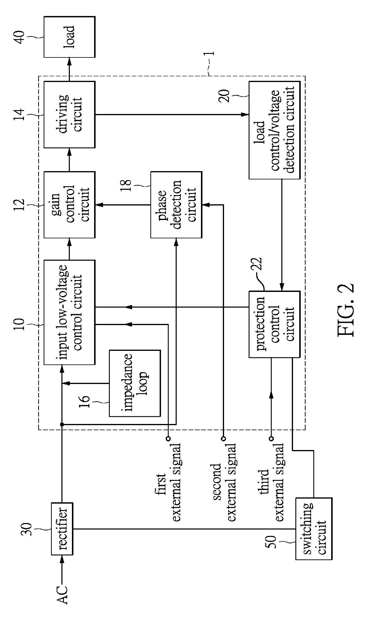
[0021]Referring to FIG. 2, FIG. 2 shows a block diagram of a drive IC for controlling a traffic light of the instant disclosure. The difference between the drive IC 1 shown in FIG. 1 and the drive IC 1 in this embodiment is that the drive IC 1 in this embodiment further comprises a load current / voltage detection circuit 20 and a protection control circuit 22. Moreover, a switching circuit 50 is connected to the drive IC 1, and the drive IC 1 further receives a third external signal. An input end of the load current / voltage detection circuit 20 is connected to the driving circuit 14, and an output end of the load current / voltage detection circuit 20 is connected to the protection control circuit 22. The load current / voltage detection circuit 20 detects the voltage and the current of the load 40. The protection control circuit 22 is connected to the input low-voltage control circuit 10 and the switching circuit 50, and receives the third external signal. The switching circuit 50 is co...
PUM
 Abstract
Description
Claims
Application Information
 - R&D
- Intellectual Property
- Life Sciences
- Materials
- Tech Scout
- Unparalleled Data Quality
- Higher Quality Content
- 60% Fewer Hallucinations
Browse by: Latest US Patents, China's latest patents, Technical Efficacy Thesaurus, Application Domain, Technology Topic, Popular Technical Reports.
© 2025 PatSnap. All rights reserved.Legal|Privacy policy|Modern Slavery Act Transparency Statement|Sitemap|About US| Contact US: help@patsnap.com


