
Method and system for service clock transparent transmission in optical transport network

a technology of optical transport network and service clock, applied in the field of communication transmission network, can solve the problems of more restrictions, and achieve the effect of relatively high quality of service clock recovered and relatively large data filled in the second buffering uni

Active Publication Date: 2015-04-07
ZTE CORP
View PDF8 Cites 0 Cited by
  • Summary
  • Abstract
  • Description
  • Claims
  • Application Information

AI Technical Summary

Benefits of technology

This approach ensures high-quality recovery of the service synchronous clock, maintaining data stability and minimizing phase-locked loop adjustments, thus meeting customer requirements for service clock quality.

Problems solved by technology

This kind of application requires that there is a fixed frequency ratio between the accessing service and the OTN service, and the transparent transferring of the multi-channel customer service clock cannot be realized, which has more restrictions in the applications.

Method used


Image

  • Method and system for service clock transparent transmission in optical transport network
  • Method and system for service clock transparent transmission in optical transport network
  • Method and system for service clock transparent transmission in optical transport network

Examples


example 1

4 Lines OTU2 are Asynchronously Mapped to the OTU3

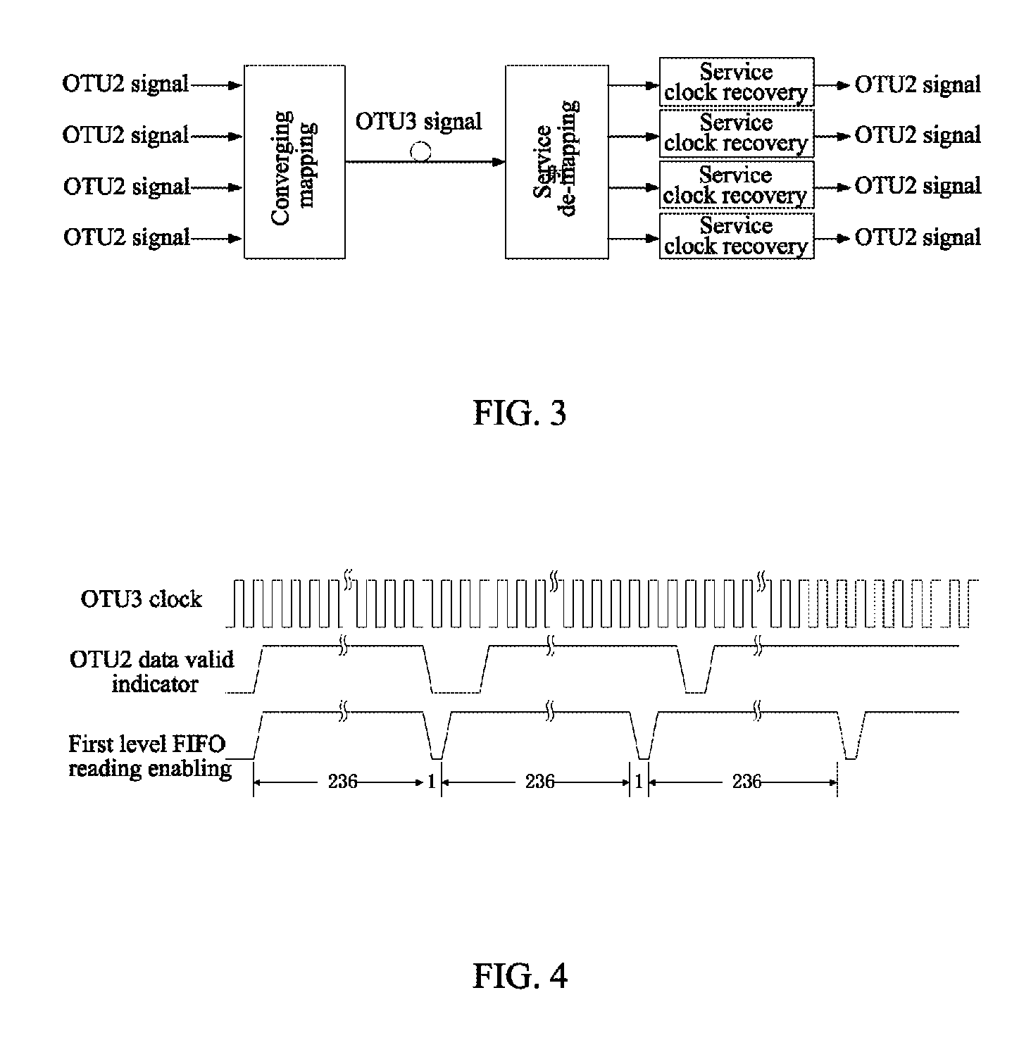
[0086]As shown in FIG. 3, 4 lines OTU2 signals are converged as 1 line OTU3 signal according to the mapping way specified in standard G.709; and in the de-converging direction, the service de-mapping module recovers 4 lines independent OTU2 data flows according to the way specified in standard G.709, and sends to each line of service clock recovery module respectively, and the service clock recovery module generates the final OTU2 service clock.

[0087]The service clock recovery module is described in detail hereinafter.

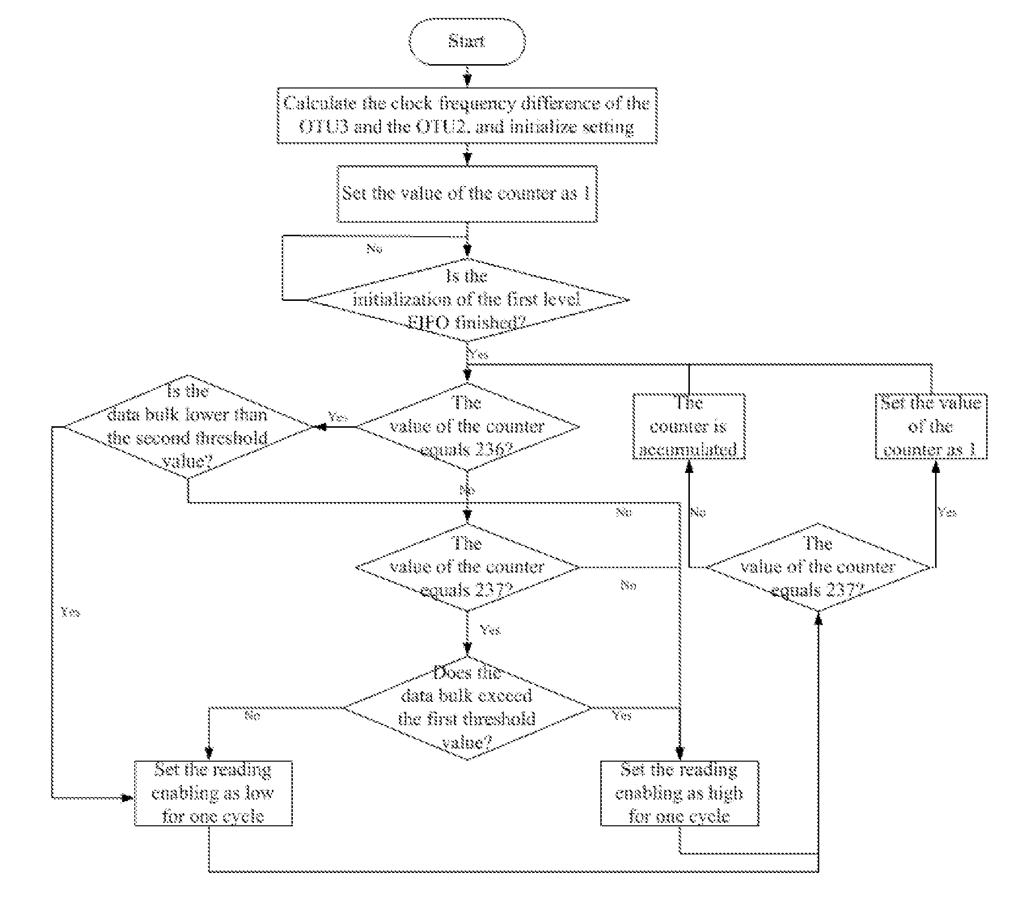
[0088]The frequency of the internal processing clock (that is, the OTN clock) of the OTU3 signal is about 155.52*255 / 236 MHz (the clock passed 256 frequency demultiplications), and the frequency of the internal processing clock (that is, the service clock) of the OTU2 signal is about 155.52*255 / 237 MHz (the clock passed 64 frequency demultiplications), which is a little slower than the internal processing clock of the O...

example 2

GE Service Clock Transportation

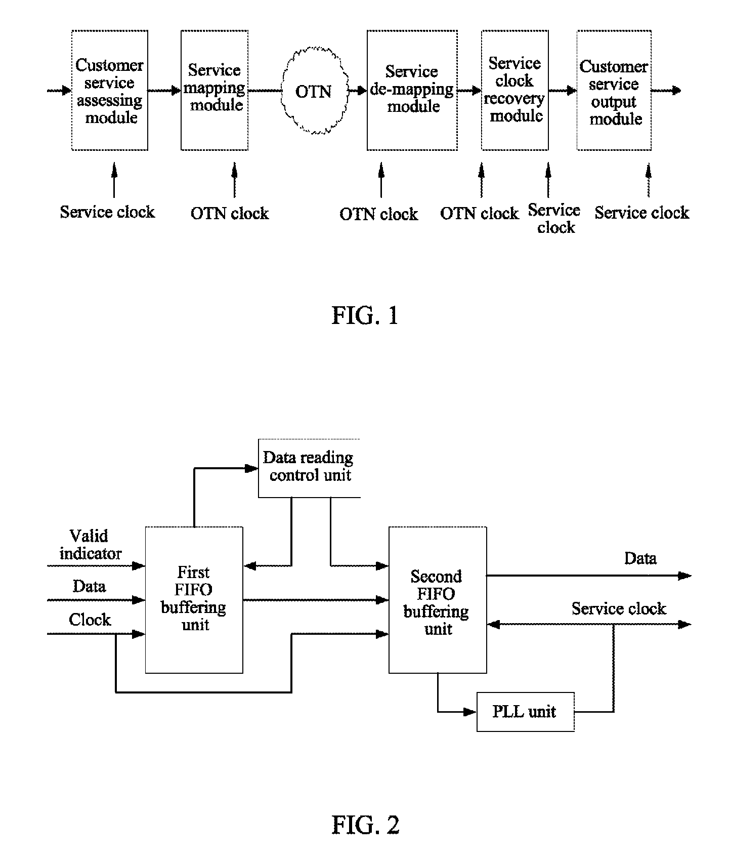
[0113]Another typical application using the present invention is to transport the Ethernet clock through the OTN, which realizes the function of synchronizing the Ethernet. As shown in FIG. 7, 8 lines GE services are mapped into the OTU2 according to the standard way after passing the common encapsulation, and in the de-mapping direction, after de-converging and common de-capsulation, the GE data flow synchronous with the OTU2 clock is obtained respectively. Through the service clock recovery unit, it can recover the GE service clock of each channel. The implementation method of the service clock recovery unit is shown in FIG. 1.

[0114]Obviously, the present invention can have a variety of other examples. Those skilled in the art can make the corresponding modifications and variations according to the present invention without departing from the spirit and essence of the present invention. And all of these modifications and the variations should be embo...


PUM


Abstract

A method and system for service clock transparent transmission in an optical transport network (OTN) are provided. The system includes a service accessing end and an OTN receiving end; the method includes the following steps: the OTN receiving end performs de-mapping operation to an OTN frame after receiving the OTN frame, and performs two-level buffering operation to the service data flow recovered therefrom, a first buffering unit performs a homogenization treatment to the service data flow and then outputs to a second buffering unit, which the second buffering unit outputs the service data flow according to the service clock after receiving the service data flow. After adopting the present invention, it is able to ensure that the quality of the recovered service clock is relatively higher, which meets the customer requirement on the related specification of the service clock.

Description

TECHNICAL FIELD[0001]The present invention relates to the field of communication transmission network, and in particular, to a method and system for service clock transparent transmission in an optical transport network (OTN).BACKGROUND OF THE RELATED ART[0002]With the development of the communication system, the OTN becomes the mainstream of the transmission network gradually, and in particular, the development of the cross switch technology based on the OTN makes the OTN develop into a bearing platform of the multiple services gradually. However, in some services or application systems, it is required to transparently transfer the client signal clock.[0003]The traditional solution is to adopt the synchronous mapping way, that is, the service clock is used to perform encapsulating to the service data flow in OTN. This kind of application requires that there is a fixed frequency ratio between the accessing service and the OTN service, and the transparent transferring of the multi-ch...

Claims


Application Information

Patent Timeline
Patent Type & Authority Patents(United States)
IPC IPC(8): H04L12/50H04J3/06H04J3/16
CPCH04J3/0623H04J3/1652H04J2203/0082
Inventor SONG, XIAOPENGYUAN, YAN
Owner ZTE CORP
Learn More