Audio-controlled image capturing
a technology of audio control and image capturing, applied in the direction of direction/deviation determination system, television system, instruments, etc., can solve the problems of user troublesome and time-consuming, easy non-optimal picture timing, user experience troublesome and time-consuming, etc., and achieve the effect of improving quality and better image quality
- Summary
- Abstract
- Description
- Claims
- Application Information
AI Technical Summary
Benefits of technology
Problems solved by technology
Method used
Image
Examples
first embodiment
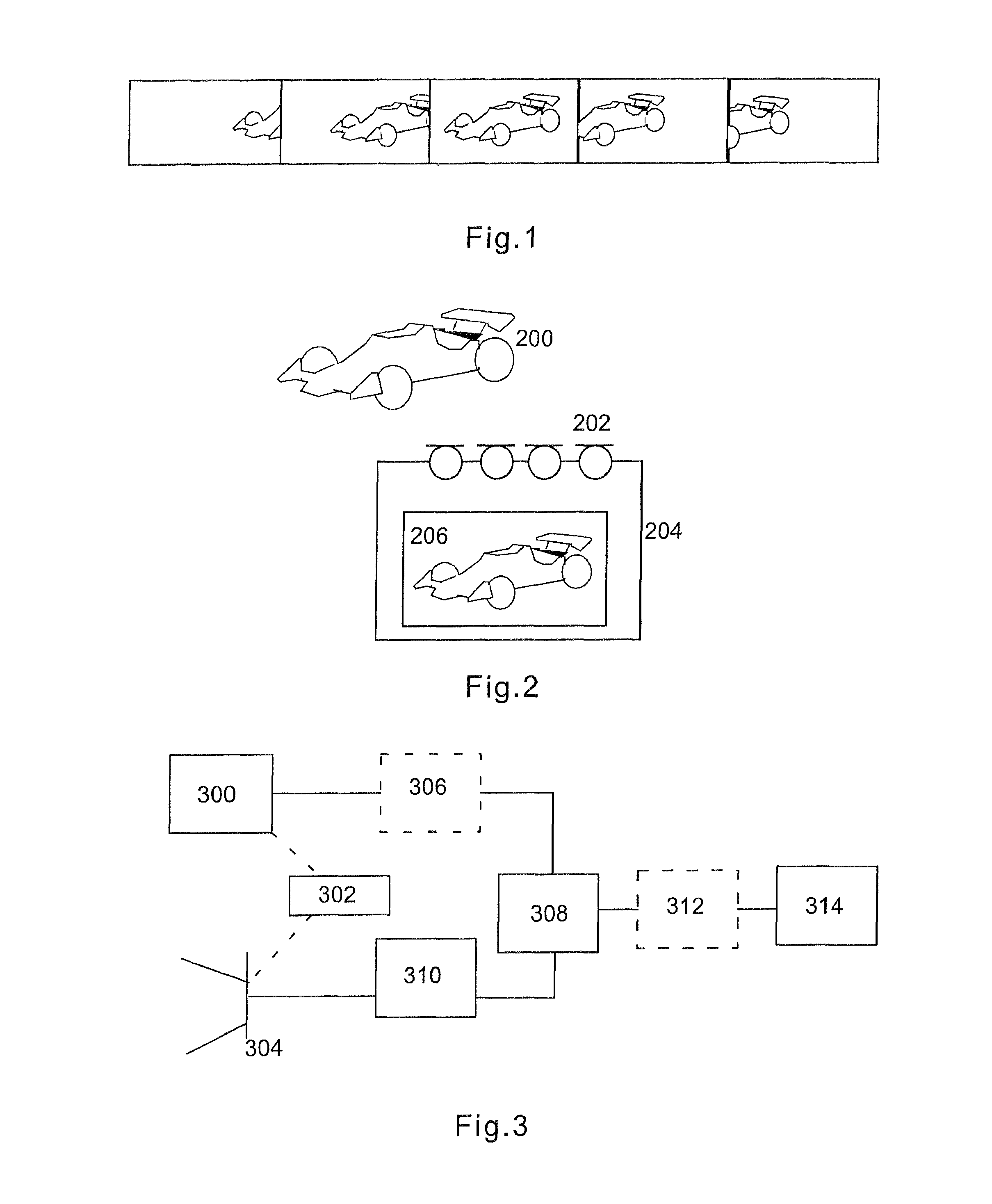
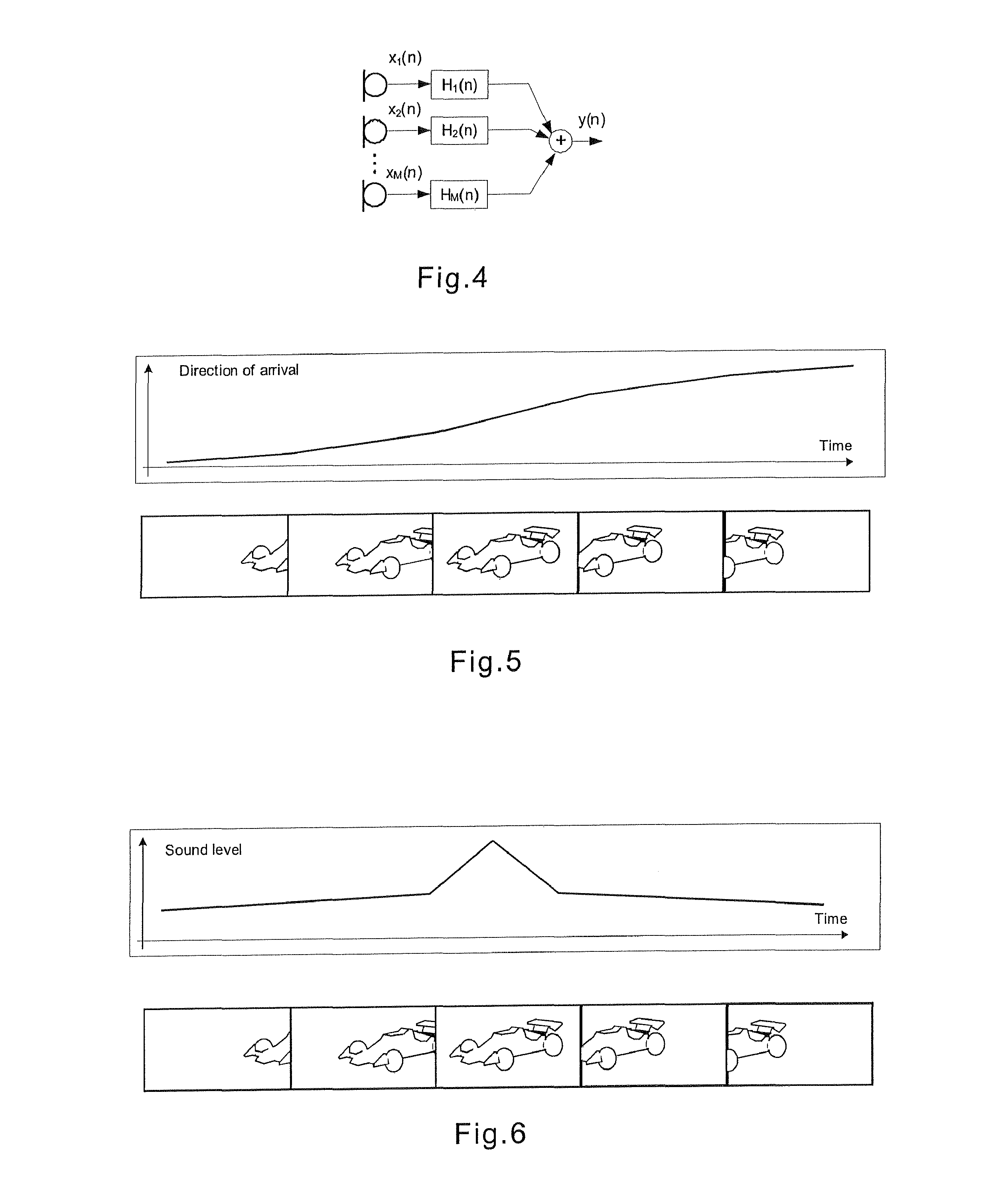
[0046] the analysis is carried out by estimating the direction of arrival of audio signal in order to determine when the sound source is in desired part of the image. According to a further embodiment, a technique referred to as beamforming can be utilised, wherein a multi-microphone array is used to estimate a direction of arrival of an audio signal.
[0047]The direction of arrival of the audio source, i.e. the location of the object within the camera viewfinder, can be extracted using beamforming algorithms. A generic microphone array consisting of a plurality (M) of microphones in the beamformer configuration is presented in FIG. 4.
[0048]The output of the microphone array of FIG. 4 is determined as
[0049]y(n)=∑m=1M∑k=0L-1Hm(n)xm(n-k),(1)
where Hm(n) is the beamforming filter and L denotes the length of the beamforming filters H1, H2, . . . , HM. The most trivial selection of the filters H1, H2, . . . , HM are delay lines, thus giving the output of the microphone array as
[0050]y...
second embodiment
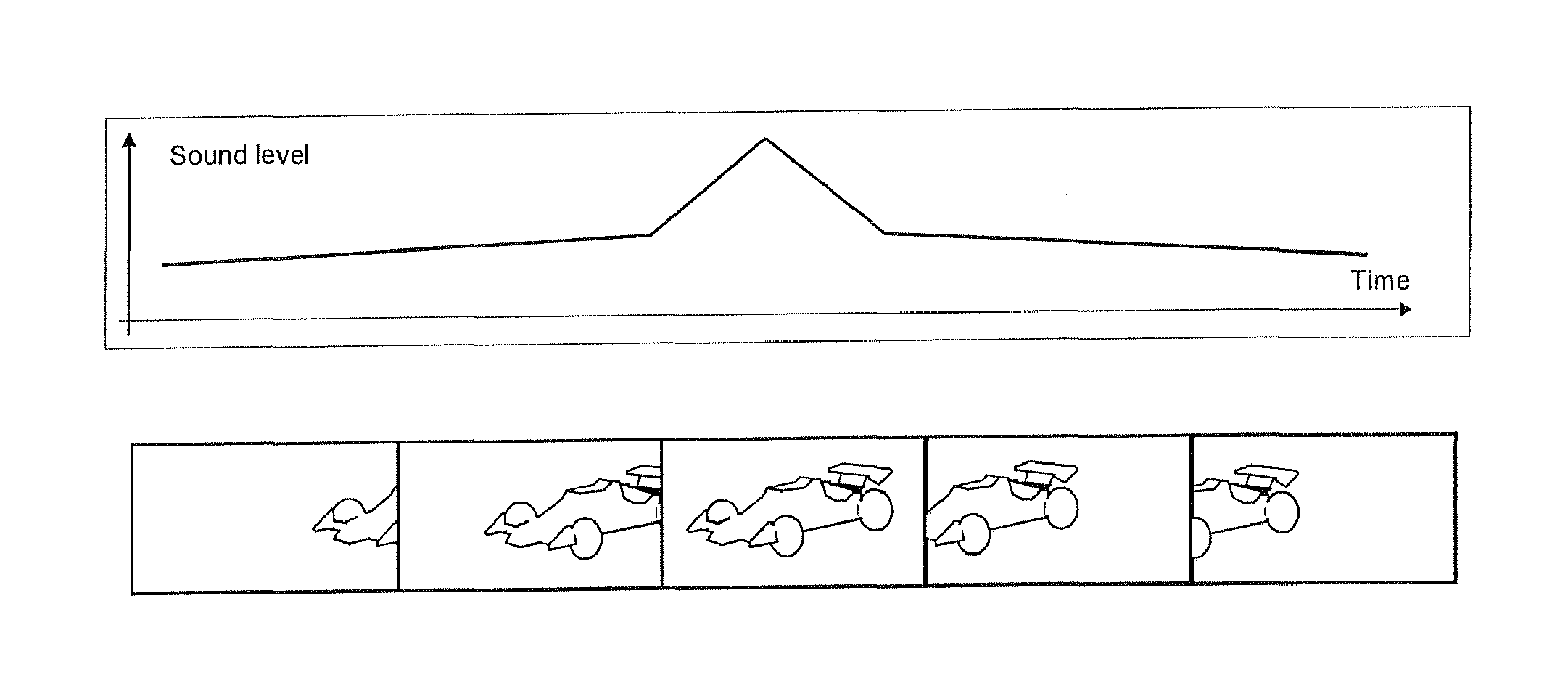
[0058] the analysis of the captured audio signal associated with the plurality of images is carried out by determining the sound level of the audio signals. This is a rather straightforward approach, wherein an abrupt change in the sound level may be used to reveal the desired moment to capture the image. The implementation does not require a directional microphone array, but only a single microphone could be used in capturing the audio signal. The microphone signal level could be determined sample by sample for example using the equation
e(n)=y(n)Ty(n) (6)
wherefrom a sound level estimation versus the time spent on capturing the plurality of images can be created.
[0059]FIG. 6 shows an example of sound level estimation for the captured audio signal corresponding to the series of images in FIG. 1. The corresponding sound level is determined for each time instant an image is captured. The scale of time axis of FIG. 6 corresponds to that of FIG. 1 as illustrated below. As can be seen, a...
third embodiment
[0060] the analysis of the captured audio signal associated with the plurality of images is carried out by determining a change in the fundamental frequency of the sound of the object. As is generally known from the physics of the Doppler effect, objects getting closer to the listener (or microphone) have a frequency shift towards higher frequencies compared to the objects getting further away from the listener. Thus, by determining the time instant when a change from a higher fundamental frequency to a lower fundamental frequency occurs, it can also be revealed when the object emitting the sound is closest to the listener, i.e. the image capturing device in this context.
[0061]The fundamental frequency of the sound of the object can be determined as an inverse of the time delay corresponding to the maximal value of autocorrelation of the dominant audio source. Hence, a simple correlation analysis of the dominant audio source is preferably carried out, wherein the delay τn within pre...
PUM
 Abstract
Description
Claims
Application Information
 - R&D
- Intellectual Property
- Life Sciences
- Materials
- Tech Scout
- Unparalleled Data Quality
- Higher Quality Content
- 60% Fewer Hallucinations
Browse by: Latest US Patents, China's latest patents, Technical Efficacy Thesaurus, Application Domain, Technology Topic, Popular Technical Reports.
© 2025 PatSnap. All rights reserved.Legal|Privacy policy|Modern Slavery Act Transparency Statement|Sitemap|About US| Contact US: help@patsnap.com


