
Firearm action and gas system

a gas system and action technology, applied in the direction of weapons, firing/trigger mechanisms, shoulder-fired small arms, etc., can solve the problems of heavy recoil, heavy receiver design, and poor effect of muzzle brak

Inactive Publication Date: 2015-04-21
TACTICAL ARMS HLDG CO
View PDF11 Cites 9 Cited by
  • Summary
  • Abstract
  • Description
  • Claims
  • Application Information

AI Technical Summary

Benefits of technology

The design results in a more compact and lighter firearm that effectively manages recoil and improves trigger accessibility, enhancing precision and reducing the overall length and weight of the weapon.

Problems solved by technology

However, because this type of weapon relies on recoil to cycle the weapon, the muzzle brake's efficiency has to be limited, otherwise it will reduce the recoil necessary to operate the reloading cycle of the weapon.
Further, because the barrel recoils inside the receiver, the receiver is heavy and complex in design, as it has to provide strong anchor points for the barrel recoiling system and the springs necessary for both the barrel and breech, that both operate separately during the cycle of operation.
Additionally, gas operated and recoil operated firearms, in their current design and configuration, impede the design of shorter and more compact larger caliber firearms.
However, conventional bullpup rifles with a trigger positioned in front of the magazine are generally not practical for larger cartridges.
The trigger may be inconveniently positioned too far forward causing excessive trigger pull or decreasing the precision of the firearm.

Method used


Image

  • Firearm action and gas system
  • Firearm action and gas system
  • Firearm action and gas system

Examples


Embodiment Construction

[0048]Before the subject invention is further described, it is to be understood that the invention is not limited to the particular embodiments of the invention described below, as variations of the particular embodiments may be made and still fall within the scope of the appended claims. It is also to be understood that the terminology employed is for the purpose of describing particular embodiments, and is not intended to be limiting. Instead, the scope of the present invention will be established by the appended claims.

[0049]In this specification and the appended claims, the singular forms “a,”“an,” and “the” include plural reference unless the context clearly dictates otherwise. Unless defined otherwise, all technical and scientific terms used herein have the same meaning as commonly understood to one of ordinary skill in the art to which this invention belongs.

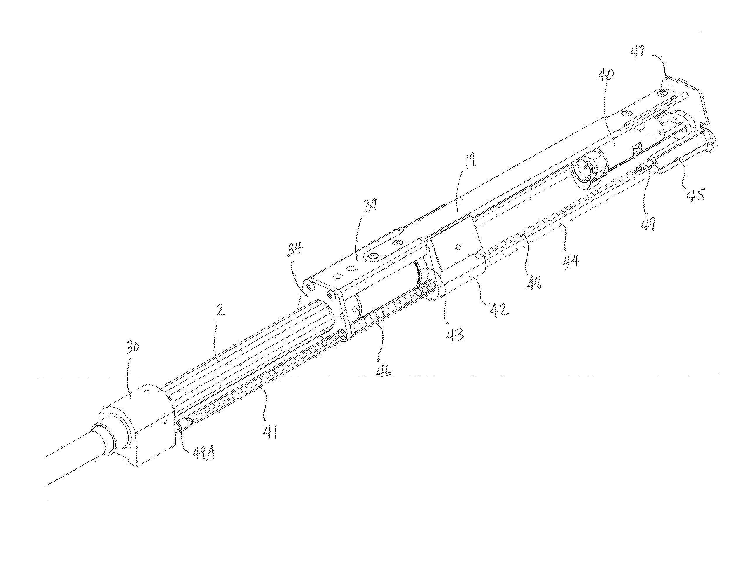
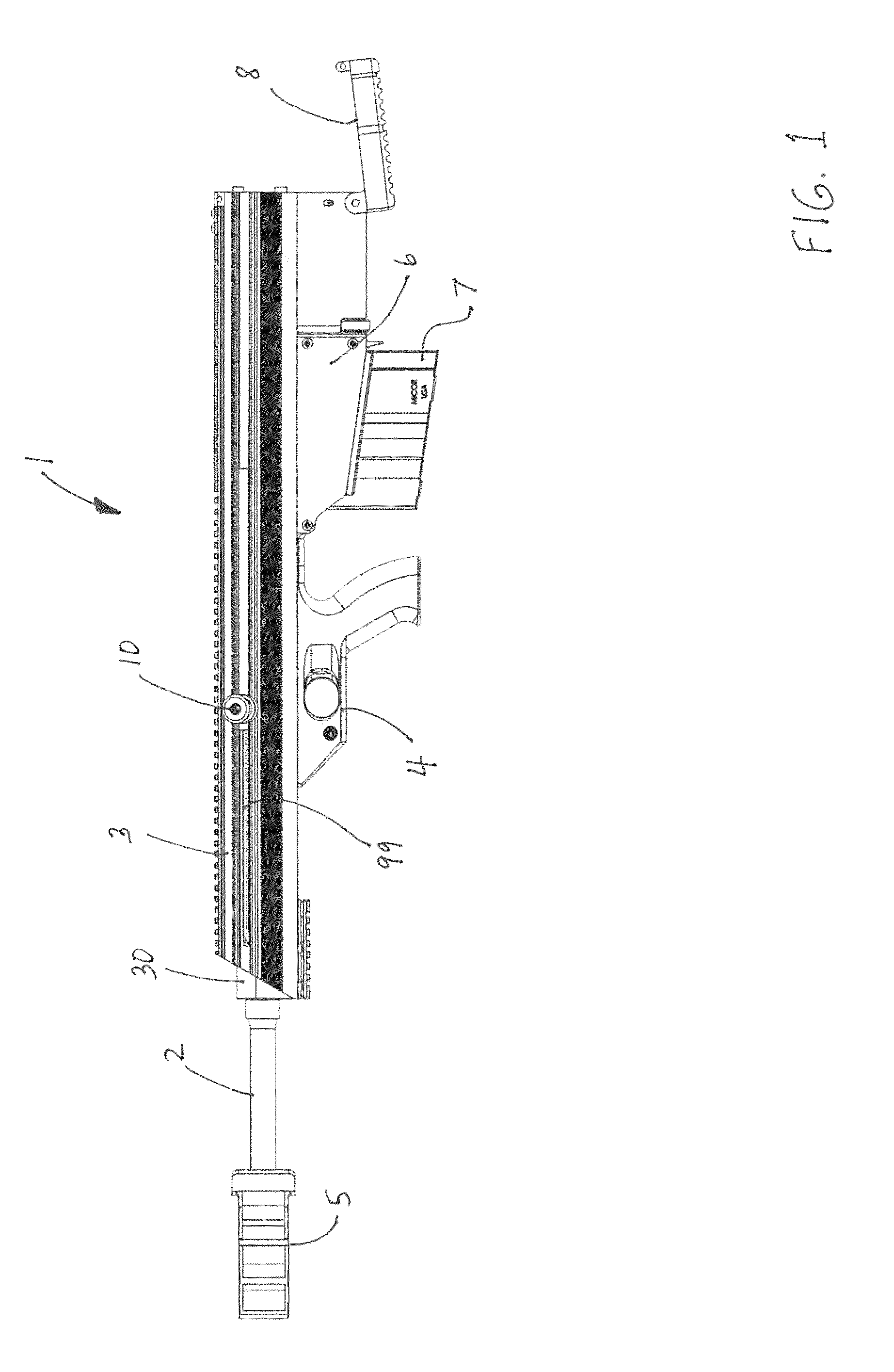
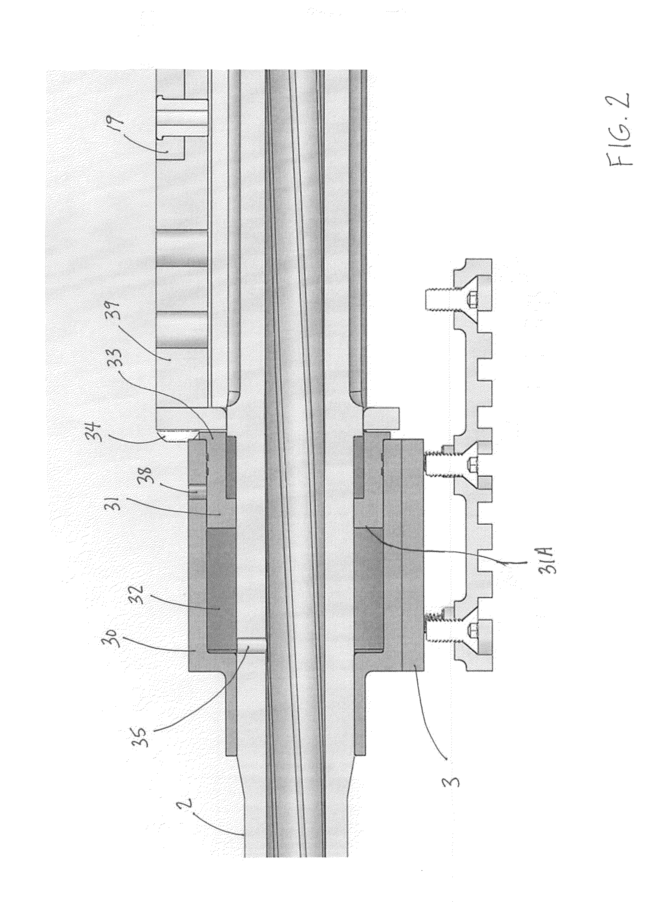
[0050]Referring to FIG. 1, there is shown a side elevation view of a bullpup rifle 1 incorporating features of the inve...


PUM


Abstract

A rifle in a bullpup configuration is provided, comprising a receiver having a trigger assembly and a magazine well, and a barrel having a barrel extension attached to the receiver. A gas assist system is attached to the barrel, including a gas housing surrounding the barrel and having an annular expansion chamber, and an annular gas piston slidably disposed within the gas housing. A thrust block is in contact with the gas piston, wherein the thrust block is slidably disposed along one or more action guide members. A rigid slide member extends from the thrust block and behind the trigger assembly. A bolt carrier and bolt are attached to the second end of the slide member and slidably disposed along one or more bolt guide members. The rifle further includes a linear hammer slidably disposed along one or more hammer guide members, and a sear assembly within the receiver having a sear member to retain the hammer, and a disconnector in communication with the sear member to release the hammer upon actuation of the trigger assembly.

Description

CROSS-REFERENCE TO RELATED APPLICATIONS[0001]This application claims the benefit under 35 U.S.C. §119(e) to provisional application Ser. No. 61 / 797,900, filed Dec. 17, 2012.STATEMENT REGARDING FEDERALLY SPONSORED RESEARCH OR DEVELOPMENT[0002]Not applicable.THE NAMES OF THE PARTIES TO A JOINT RESEARCH AGREEMENT[0003]Not applicable.BACKGROUND OF THE INVENTION[0004]1. Field of the Invention[0005]The present invention relates to self-loading or semi-automatic firearms having an improved action and gas system, and more particularly to such firearms having a bullpup configuration.[0006]2. Description of Related Art[0007]Firearms, particularly those that are built to fire powerful cartridges such as the .50 BMG (.50 caliber Browning Machine Gun) round requires various devices to help reduce the recoil to an acceptable level while operating the weapon. Firearms that operate as above are known either as recoil or gas operated.[0008]A recoil operated firearm generally allows the barrel (locke...

Claims


Application Information

Patent Timeline
Patent Type & Authority Patents(United States)
IPC IPC(8): F41A5/00F41A3/12F41A5/20F41A19/10F41A19/12F41A19/13F41A19/14F41A21/36F41C7/00
CPCF41A5/20F41A19/12F41A19/13F41A19/14F41A3/12F41A19/10F41A21/36F41C7/00
Inventor ST. GEORGE, CHARLES
Owner TACTICAL ARMS HLDG CO
Learn More