
Internal combustion engine and compressor or pump with rotor and piston construction, and electrical generator pneumatically driven by same

a technology of internal combustion engine and compressor or pump, which is applied in the direction of engines with rotating cylinders, mechanical equipment, transportation and packaging, etc., can solve the problems of less efficiency and more pollution

Active Publication Date: 2015-04-21
NOVAK ROBERT J
View PDF14 Cites 3 Cited by
  • Summary
  • Abstract
  • Description
  • Claims
  • Application Information

AI Technical Summary

Benefits of technology

The invention is an internal combustion engine with a stator and rotor that rotate to produce power. The engine has cylindrical bores and pistons that seal with the stator to create combustion chambers. A spark plug initiates combustion in the chambers, and air and fuel are fed into the chambers through a fuel injector and air and fuel intake. The engine also has an air and fuel intake with a breaker arm and a valve to control air and fuel delivery. An air compressor and storage tank are used to deliver and regulate air pressure. The engine also includes a water separator to remove water droplets from the air. The cylindrical bores and pistons are positioned to optimize engine performance. The technical effects of the invention include improved fuel efficiency, reduced emissions, and improved engine performance.

Problems solved by technology

A two-stroke engine completes its combustion cycle once every crankshaft rotation, but such engines are generally considered to be less efficient and create more pollution.

Method used


Image

  • Internal combustion engine and compressor or pump with rotor and piston construction, and electrical generator pneumatically driven by same
  • Internal combustion engine and compressor or pump with rotor and piston construction, and electrical generator pneumatically driven by same
  • Internal combustion engine and compressor or pump with rotor and piston construction, and electrical generator pneumatically driven by same

Examples


first embodiment

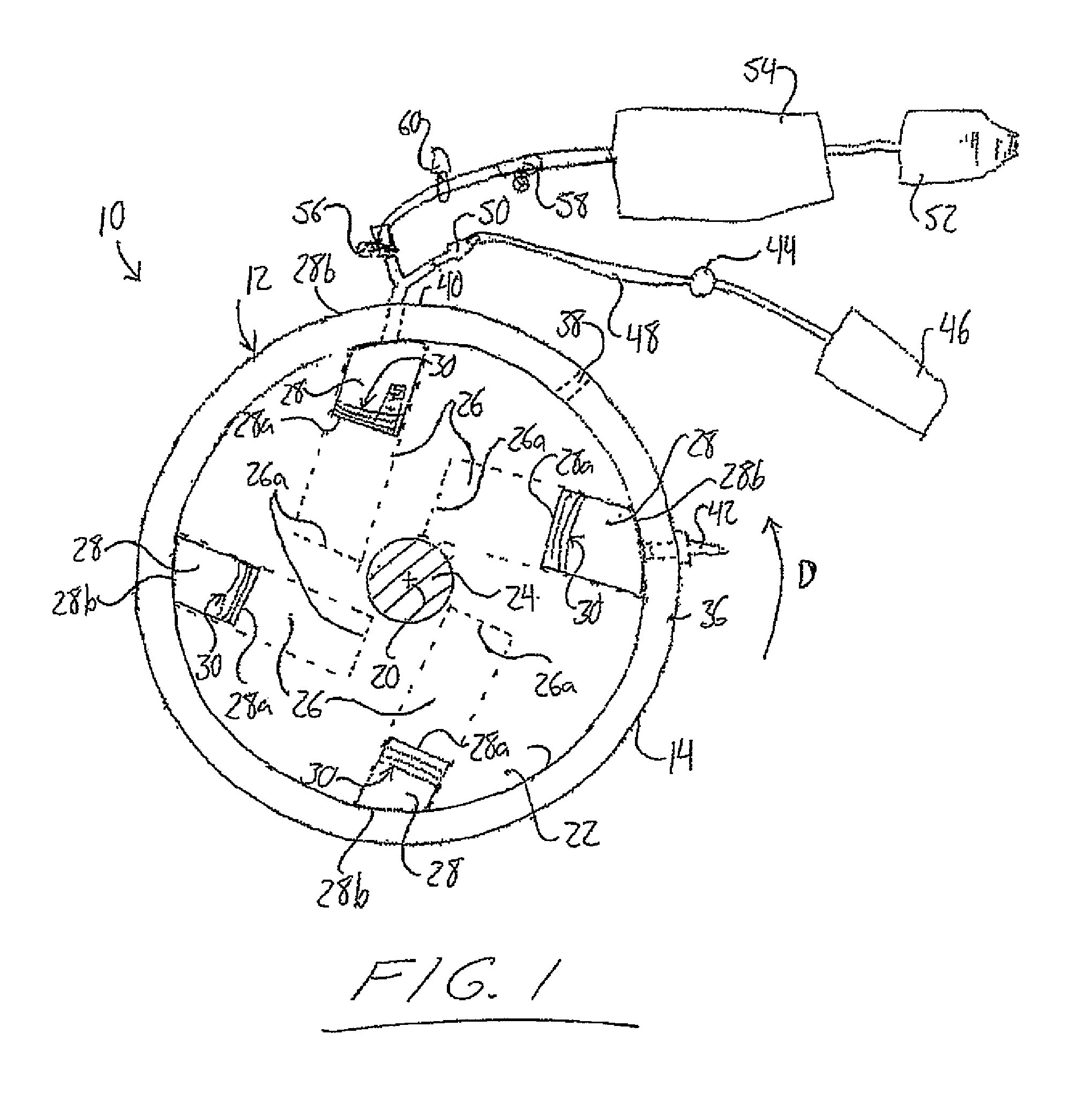
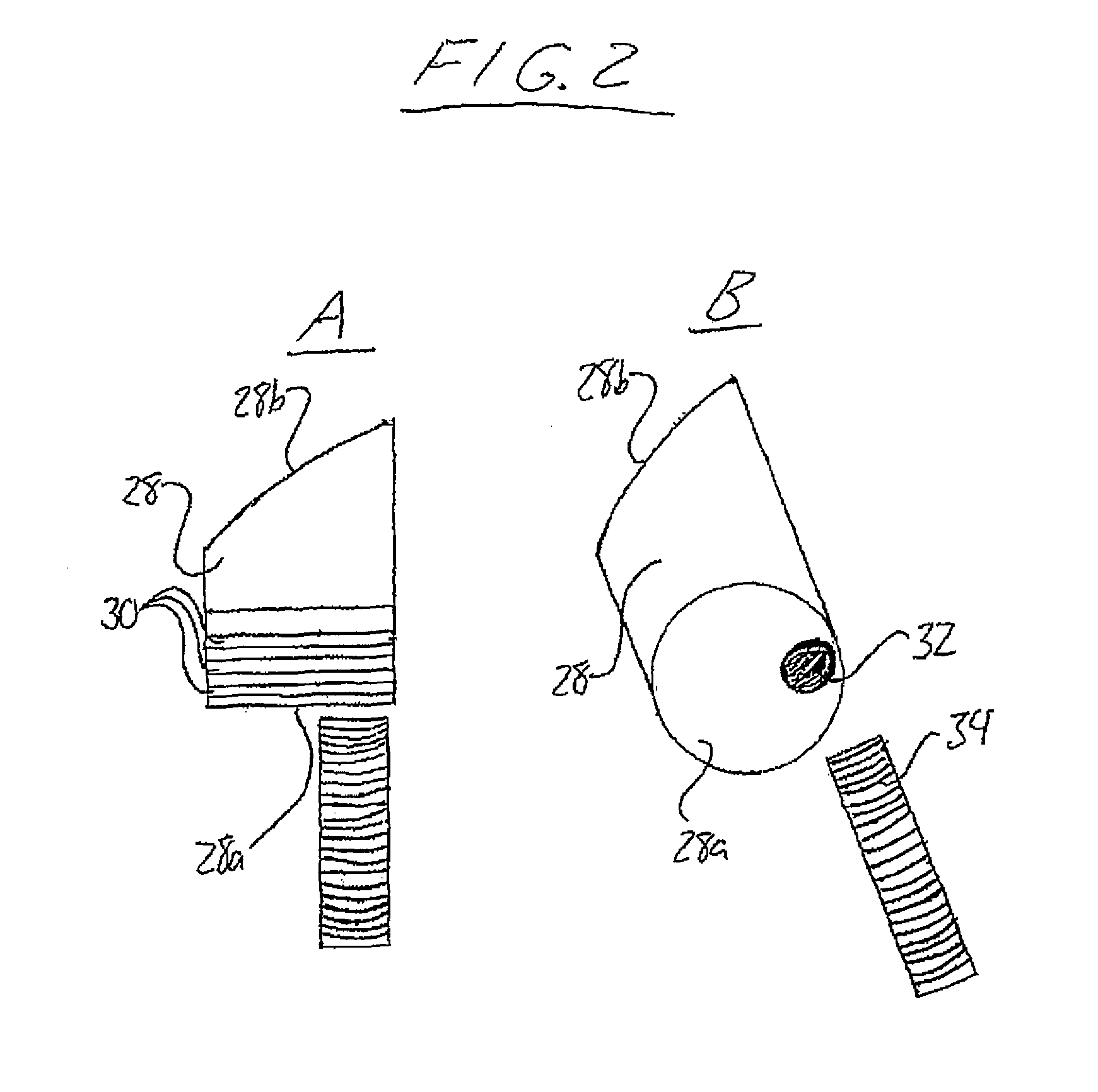
[0096]FIG. 1 schematically shows an internal combustion engine 10 according the present invention. The engine features a stator or housing 12 in the form of a cylindrical outer peripheral wall 14 closed off at opposite ends of its cylindrical shape by circular front and rear end walls 16, 18, one of which has been removed in FIG. 1 to illustrate contents of the stator's interior and the other of which is not visible in that particular figure. The peripheral wall 14 of the stator closing concentrically about a central axis 20 forms boundaries of the stator's cylindrical interior space of circular cross section. Within the interior space of the stator 12, the engine 10 features a rotor 22 in the shape of a short cylinder of circular cross section concentric with the cylindrical peripheral wall 14 of the stator 12. The rotor 22 has a diameter slightly less than the inner diameter of the peripheral stator wall 14 and is fixed on a rotatable shaft 24 extending concentrically along the ce...

second embodiment

[0114]Applicant conceives that the igniting and injecting of fuel at the same time causing a faster rotation, with more pressure, and that when the motor is rotating at a comfortable speed, the fuel injector can be shut off, and the collection of used air in the air tank from the compressor, will keep the rotor rotating at the same rpm's. Able to pump gas or liquid fluids and provide direct rotational output, the second embodiment engine would be operable to run or turn multiple turbines, gen-heads, rotors, and other equipment. It will be appreciated that the number of cylinders in the rotor may be increased or decreased, and the angular spacing and oblique angling of the cylinders may also be varied without change to the principles under which the rotation of the rotor is driven.

third embodiment

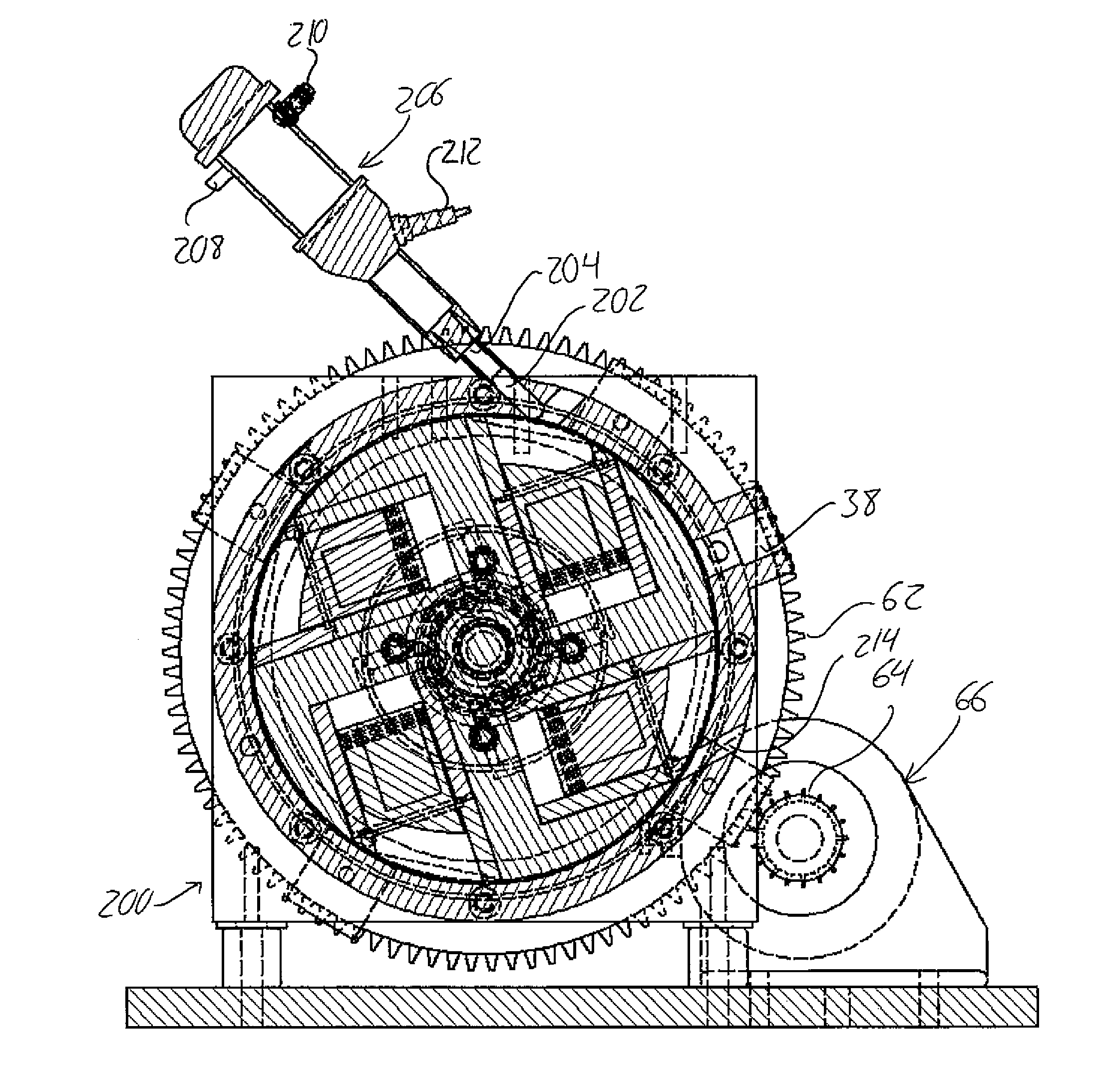
[0115]FIG. 5 shows a third embodiment engine 200 of the present invention that features substantially the same configuration of free-sliding pistons disposed in cylindrical bores disposed in the rotor at oblique angles relative to the radii of the rotor where the bores extend into the rotor periphery. These pistons are again free to slide fully from the bottom inner end of their bores fully out to the periphery of the rotor, where the end faces of the pistons are shaped to conform to the cylindrical inner surface of the stator housing. The pistons are free sliding in that lack of any mechanical connection or link to the rotor other than the sliding interface between the piston periphery and the surrounding cylindrical wall in the respective bore in the rotor.

[0116]The third embodiment differs from the preceding embodiments in that the stator's intake port and separate spark plug port have been replaced with a single opening 202 through the cylindrical peripheral wall of the stator, ...


PUM


Abstract

Unique engines, air compressors, and pneumatically driven electrical generators are disclosed. The engine employs a rotor having a number of pistons slidably disposed within respective cylinder bores extending into the rotor periphery. As the rotor spins within a stator, each cylinder bore passes a combustion stage at which the piston is driven further into the rotor toward a bottom of the respective cylinder bore. Valves at the bottom of the cylinder discharge air that is compressed by this piston downstroke, and admit new intake air during an opposing upstroke. The unit thus operates as a self driven compressor, or engine-compressor combination, and the compressed air may be used to pneumatically drive a turbine of an electrical generator. A carbon splitter dissociates carbon and oxygen molecules from the carbon dioxide in the air downstream of the generator turbine, reducing the overall carbon dioxide output of the system.

Description

FIELD OF THE INVENTION[0001]The present invention relates generally to internal combustion engines, and more particularly to an internal combustion engine with a novel design in which a plurality pistons reciprocate within a spinning rotor to drive rotation of an output shaft or pump or compress a fluid.BACKGROUND OF THE INVENTION[0002]Modern internal combustion engines use a four stage cycle to obtain power for rotational motion from the ignition of a combustible fuel, such as gasoline. The first stage is intake wherein a mixture of air and fuel is introduced into a combustion chamber. The second stage is the compression of this mixture within the combustion chamber in preparation for the next stage, the power stage. In the power, or combustion stage, the compressed air and fuel mixture is ignited and the combustion rapidly increased the pressure within the combustion chamber. This pressure is exerted on a movable mechanical part, for example a linearly displaceable piston or a rot...

Claims


Application Information

Patent Timeline
Patent Type & Authority Patents(United States)
IPC IPC(8): F02B57/08F01B13/06F01B13/04F02B57/00F02B63/04
CPCF02B57/00F02B63/042F01B13/045
Inventor NOVAK, ROBERT J.
Owner NOVAK ROBERT J
Learn More