
Flow mixer and conditioner

a flow mixer and conditioner technology, applied in the direction of mixing, chemistry apparatus and processes, mixers, etc., can solve the problems of excessive pump component degradation, adversely affecting the performance and protection of flow meters, and flow conditioning devices, so as to reduce shipping costs and save shipping and material costs

Active Publication Date: 2015-04-21
FLUID COMPONENTS INTERNATIONAL
View PDF13 Cites 20 Cited by
  • Summary
  • Abstract
  • Description
  • Claims
  • Application Information

AI Technical Summary

Benefits of technology

The patent text discusses various improvements that can be made to flow meters to increase their accuracy and lifespan. These improvements include reducing distortion in the velocity flow profile, eliminating swirl, reducing stratification, and eliminating random vortices. These improvements can lead to better performance of critical process equipment like pumps and compressors. The text also mentions that pumps can be protected from damage by mixing and destratifying the flowing media. Overall, the patent text aims to provide a better understanding of flow meters and the improvements that can be made to them.

Problems solved by technology

Disturbances in media flowing within a conduit adversely affect flow meter performance and pump protection by creating, for example, swirl and irregular flow profiles.
The resulting errors often exceed the flow meter manufacturer's published accuracy specifications and can lead to cavitation and excessive pump component degradation.
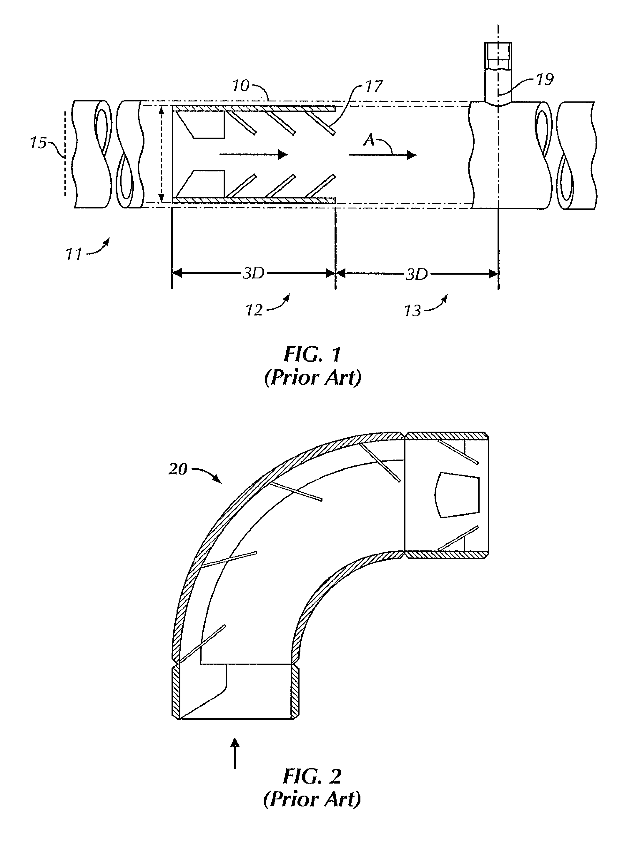
Flow conditioning devices, such as shown in FIG. 1, that are used for conduits having sizes above about six inches in diameter are heavy, expensive to ship, and require expertise to handle and install.
This situation becomes increasingly more difficult and costly as the size of the conduit, and therefore, the conditioner device, increases in diameter.
Other flow conditioning devices include tube bundles, which do not correct the velocity profile distortion, and perforated plates, which are useful but tend to cause excessive pressure drop, do little mixing, and are not particularly useful in pump protection.

Method used


Image

  • Flow mixer and conditioner
  • Flow mixer and conditioner
  • Flow mixer and conditioner

Examples


Embodiment Construction

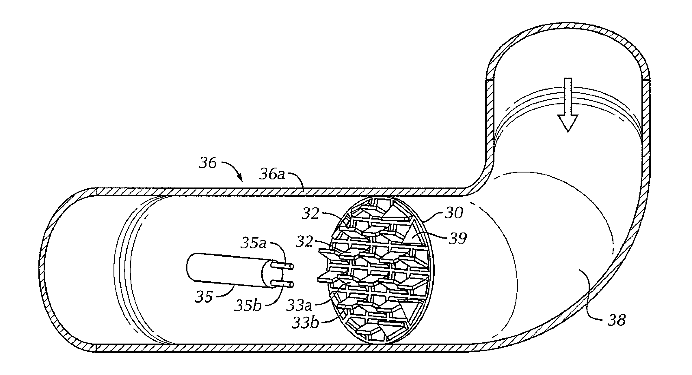
[0008]Various embodiments discussed herein address the shortcomings of the prior art. These embodiments provide improvements over the prior art by reducing, and some instances even eliminating distorted or asymmetric velocity flow profiles and other variable disturbances in flowing media to enable flow meters to have improved accuracy, enhanced mixing, and extended life span of critical process equipment, such as pumps and compressors. These embodiments also improve velocity flow profiles by reducing swirl, reducing stratification, and eliminating random vortices, thereby improving the accuracy of turbine, orifice plate, sonic, thermal, ultrasonic, magnetic, vortex shedding, pitot tube, annular, sonar, differential pressure, and other flow metering devices. Additionally, pumps are protected by mixing and destratifying the flowing media. The term, “meter,” will occasionally be employed herein to include each and all of the devices or instruments already enumerated.

[0009]Flow disturba...


PUM


Abstract

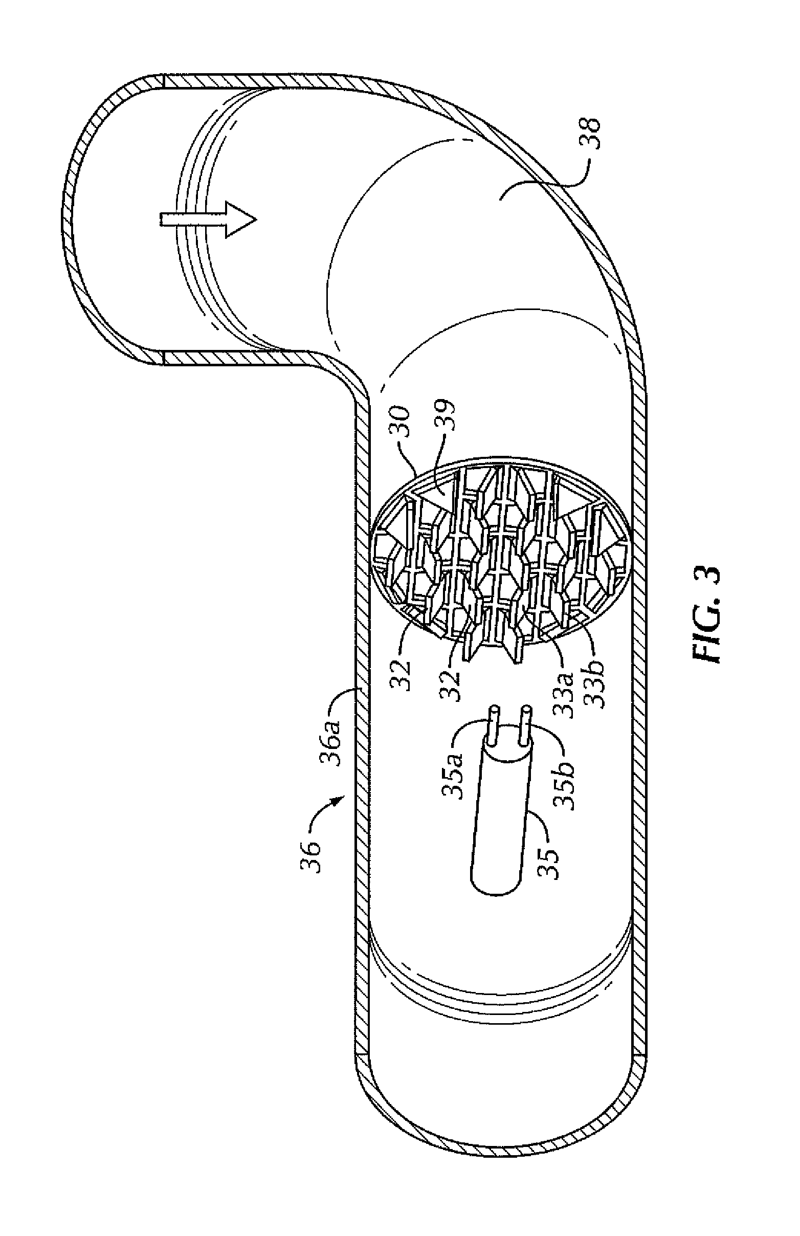
A flow mixer and conditioner for use within a conduit conditions flowing media within the conduit to provide a swirl-free, symmetric, and reproducible velocity profile regardless of upstream flow distortions, disturbances, or anomalies. Tabs are cut from a single plate and bent or affixed to provide mixing and conditioning of the flowing media. Single tabs or tab pairs emanating from common vertices can be formed so that they diverge in, or against, the direction of flowing media. The flow conditioner requires as little as three pipe diameters downstream and upstream to mix and condition the flow stream allowing close placement to elbows, valves, tees, and other disturbances typically seen in industrial plants.

Description

FIELD OF THE INVENTION[0001]The invention relates generally to devices that mixes or conditions, or both, media flowing within a conduit, and more particularly, to devices to be used upstream from flow meters, pumps, compressors, reactors, or other critical equipment requiring a uniformly mixed, swirl-free, symmetric, reproducible, and destratified velocity profile regardless of upstream stratification, flow distortions, disturbances, or anomalies.BACKGROUND OF THE INVENTION[0002]Disturbances in media flowing within a conduit adversely affect flow meter performance and pump protection by creating, for example, swirl and irregular flow profiles. The resulting errors often exceed the flow meter manufacturer's published accuracy specifications and can lead to cavitation and excessive pump component degradation. Flow conditioning, such as may be accomplished by tube bundles or perforated plates, among others, is known within the prior art to remove swirl and create symmetric and reprodu...

Claims


Application Information

Patent Timeline
Patent Type & Authority Patents(United States)
IPC IPC(8): B01F5/06
CPCB01F5/0618B01F5/0616B01F2005/0627B01F2005/0639B01F25/43163B01F25/4316B01F25/4315B01F25/431974B01F25/40
Inventor MCQUEEN, MALCOLM M.LUNDBERG, DONALD G.
Owner FLUID COMPONENTS INTERNATIONAL
Learn More