Vibrating reed, electronic device, and electronic apparatus

a technology of vibrating reeds and electronic devices, applied in the field of vibrating reeds, can solve the problems of deteriorating vibration efficiency of vibrating arms or temperature characteristics of resonant frequencies, and achieve the effect of reducing vibration leakag

Inactive Publication Date: 2015-04-21
SEIKO EPSON CORP
View PDF12 Cites 7 Cited by
  • Summary
  • Abstract
  • Description
  • Claims
  • Application Information

AI Technical Summary

Benefits of technology

[0009]An advantage of some aspects of the invention is to provide a vibrating reed that can reduce vibration leakage even when the size thereof is reduced, and an electronic device and an electronic apparatus both using the vibrating reed.
[0012]With the above configuration, the coupling portion has a shape bent also in a thickness direction. Due to this, a vibration propagation path in the coupling portion also bends in the thickness direction of the coupling portion, conforming to the shape of the coupling portion in the thickness direction. Therefore, without enlarging the coupling portion, the vibration propagation path on the coupling portion from the vibrating body to the support portion can be lengthened. Hence, the amount of damping of vibration from the vibrating body can be further increased, even when the vibrating reed is reduced in size, to reduce vibration leakage to the support portion.Application Example 2
[0020]With the above configuration, a vibrating reed of a so-called WT-type that can reduce the vibration leakage to the support portion is provided.Application Example 6
[0023]With the above configuration, an electronic apparatus with reduced vibration leakage is provided.

Problems solved by technology

Due to this, the excitation efficiency of the vibrating arm or a temperature characteristic of a resonant frequency is deteriorated.

Method used


Image

  • Vibrating reed, electronic device, and electronic apparatus
  • Vibrating reed, electronic device, and electronic apparatus
  • Vibrating reed, electronic device, and electronic apparatus

Examples


Embodiment Construction

[0036]Hereinafter, the invention will be described in detail using an embodiment shown in the drawings. However, constituent elements, kinds, combinations, shapes, relative arrangements thereof, and the like described in this embodiment are not intended to limit the scope of the invention but are merely explanatory examples unless a specific description is provided. In the drawings and the following description, an X-axis (first direction), a Y-axis (second direction), and a Z-axis are perpendicular to one another.

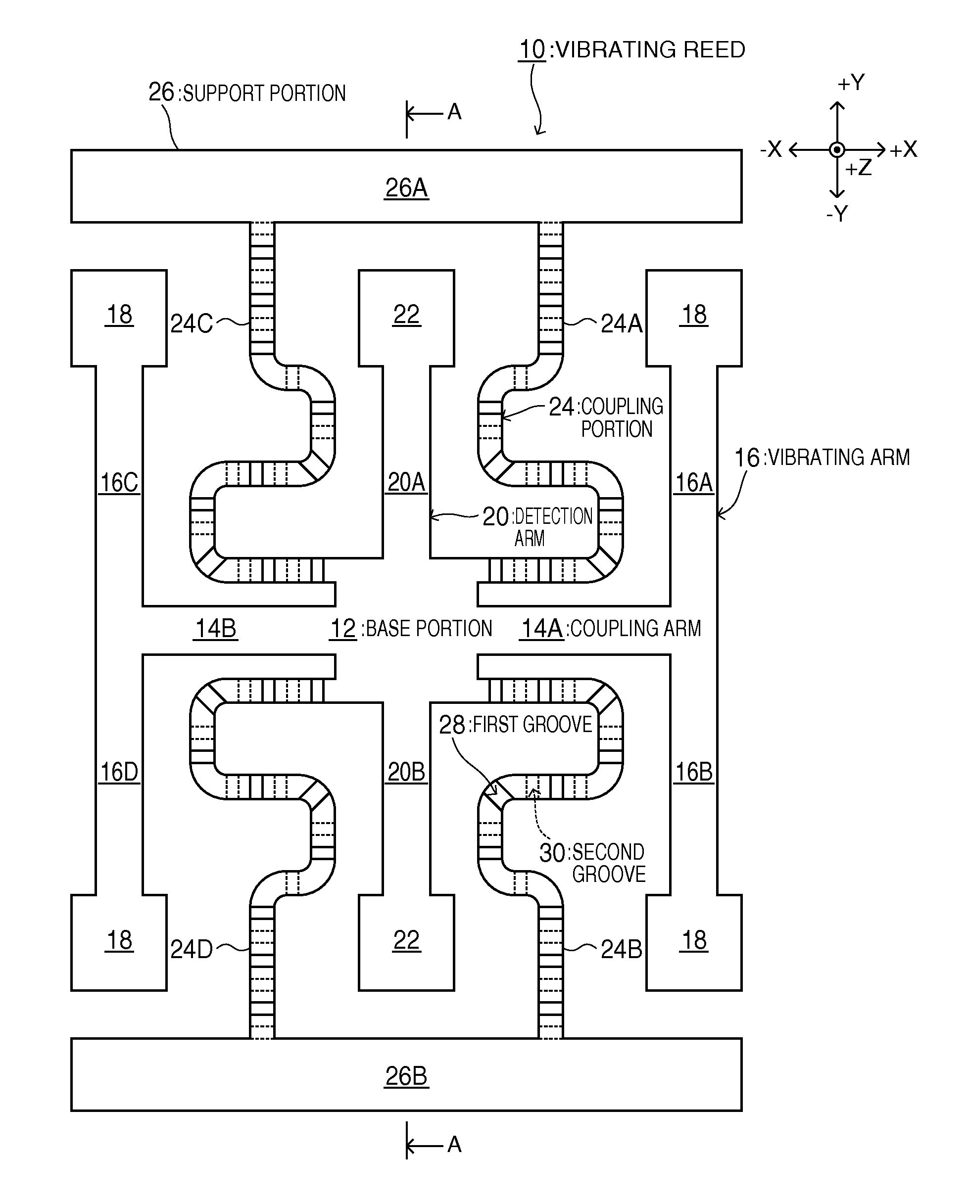
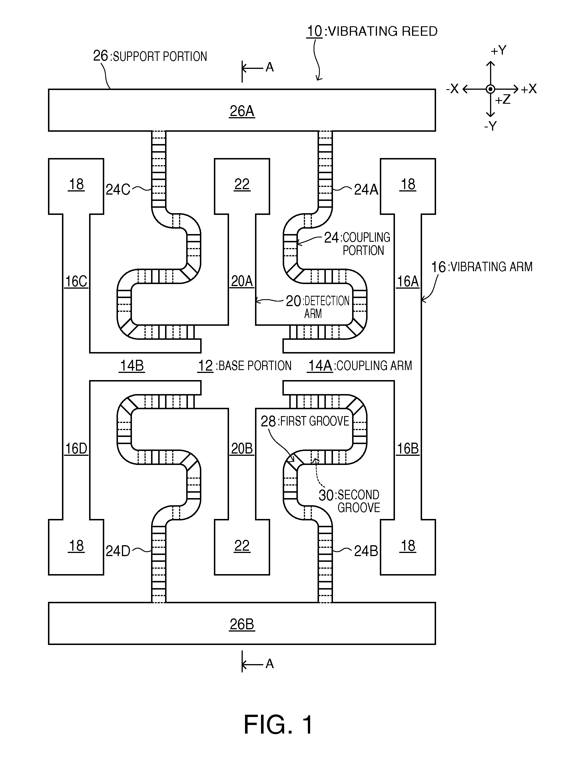
[0037]FIG. 1 shows a plan view of a vibrating reed of the embodiment. The vibrating reed of the embodiment is formed of a piezoelectric material such as quartz crystal. As shown in FIG. 1, the vibrating reed is a gyro sensor of a so-called WT-type. The vibrating reed 10 is configured of a vibrating body (a base portion 12, a vibrating arm 16 (16A to 16D), a detection arm 20 (20A and 20B), and the like), a support portion 26 (26A and 26B), and a coupling portion 24.

[0038]Al...


PUM


Abstract

A vibrating reed includes a vibrating body (a base portion, a vibrating arm, and a detection arm) and a support portion that supports the vibrating body via a plate-like coupling portion. In both principal surfaces of the coupling portion, grooves (a first groove and a second groove) are disposed. The first groove arranged in one of the principal surfaces of the coupling portion and the second groove arranged in the other principal surface are arranged at positions different from each other in plan view.

Description

BACKGROUND[0001]1. Technical Field[0002]The present invention relates to a vibrating reed, and particularly, to a vibrating reed with reduced vibration leakage, and an electronic device and an electronic apparatus both using the vibrating reed.[0003]2. Related Art[0004]Heretofore, as an angular velocity sensor for detecting a rotational angular velocity of a rotating system, a vibration-type gyro sensor using a piezoelectric vibrating reed or a vibrator having a piezoelectric vibrating reed accommodated in a container has been used. The vibration-type gyro sensor is used for a car navigation system, camera shake detection of a still camera, and the like.[0005]For the piezoelectric vibrating reed used for the vibration-type piezoelectric gyro sensor, a piezoelectric vibrating reed configured of a plurality of vibrating arms extended in the same plane and a base portion coupling the vibrating arms together is used. The vibration-type piezoelectric gyro sensor drives and vibrates the p...

Claims


Application Information

Patent Timeline
Patent Type & Authority Patents(United States)
IPC IPC(8): H01L41/053G01C19/5607
CPCH01L41/053G01C19/5607H10N30/88
Inventor YAMAGUCHI, KEIICHIOSAWA, SEIJIOGURA, SEIICHIROKIKUCHI, TAKAYUKI
Owner SEIKO EPSON CORP
Why Eureka
Try Eureka