Image processing apparatus and image processing method

a technology of image processing and image processing, applied in the field of mixed reality technology, can solve the problems of incongruity generated, inaccurate outline of overlap between virtual objects and physical objects, bulky devices used to measure the depth information of physical objects in real time, etc., and achieve the effect of reducing the number of incongruity generated

Active Publication Date: 2015-04-21
CANON KK
View PDF17 Cites 7 Cited by
  • Summary
  • Abstract
  • Description
  • Claims
  • Application Information

AI Technical Summary

Benefits of technology

[0037]The present invention has been made in consideration of the above-described problems, and has as its object to provide a technique of reducing various senses of incongruity generated upon superimposing a physical object and a virtual object.

Problems solved by technology

However, a device to be used to measure the depth information of a physical object in real time is bulky and expensive.
In addition, if the resolution of depth information is insufficient, the outline of overlap between the virtual object and the physical object may be inaccurate.
This phenomenon gives unnatural binocular rivalry to the observer and produces a sense of incongruity.
However, when these objects having different depths are presented in a stereoscopic vision, the observer may have the above-described sense of incongruity.

Method used


Image

  • Image processing apparatus and image processing method
  • Image processing apparatus and image processing method
  • Image processing apparatus and image processing method

Examples


first embodiment

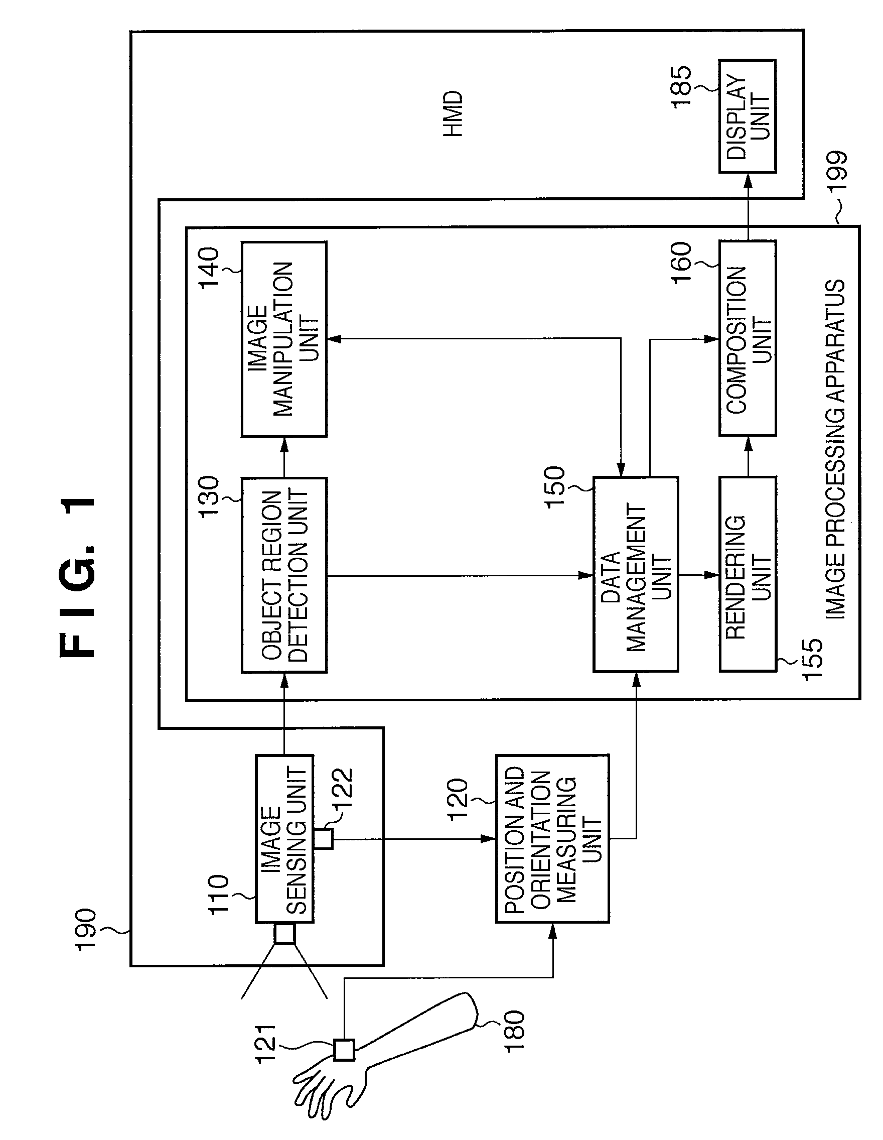
[0076]FIG. 1 is a block diagram showing the functional arrangement of a system according to this embodiment. As shown in FIG. 1, the system according to this embodiment includes an HMD 190, position and orientation measuring unit 120, and image processing apparatus 199.

[0077]The HMD 190 will be described.

[0078]The HMD 190 includes an image sensing unit 110 and a display unit 185.

[0079]The image sensing unit 110 senses a movie of physical space. Each sensed frame image (physical space image) is input to the image processing apparatus 199. In this embodiment, the image sensing unit 110 includes image sensing units corresponding to the right and left eyes of the observer (user) who wears the HMD 190 on the head. However, the two eyes may share one image sensing unit.

[0080]A sensor 122 for measuring the position and orientation of the image sensing unit 110 is attached to the image sensing unit. A sensor 121 similar to the sensor 122 is attached to a hand 180 (physical object of interes...

second embodiment

[0130]In the first embodiment and its first and second modifications, a target region in a physical space image is shaded aiming at reducing the sense of shift between a physical object and a virtual object. In the second embodiment, a sense of incongruity in a binocular stereoscopic vision which is generated upon superimposing a virtual object expressing the interior of a physical object on the physical object (rendering a stereoscopic CG image) is reduced.

[0131]In this embodiment, when a stereoscopic vision is presented by superimposing an internal structure virtual object shown in FIG. 8 on a mock-up 1310 shown in FIG. 5, the region in a virtual object 610 representing a camera exterior shown in FIG. 6 is shaded to reduce the sense of incongruity in the binocular stereoscopic vision.

[0132]More specifically, the virtual object 610 representing a camera exterior is arranged at the position and orientation of the mock-up 1310. After that (after arrangement), the projection region of...

first modification

of Second Embodiment

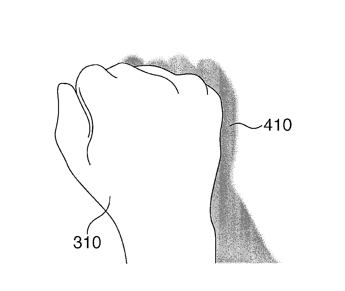
[0138]In the second embodiment, the projection region is set as the region to be shaded. If masking of a hand is necessary, as shown in FIG. 9 of non-patent reference 3, “shading processing” should sometimes be inhibited for the hand region included in the shading target region.

[0139]To cope with this situation, an object region detection unit 130 can inhibit “shading processing” of the hand region by excluding a portion corresponding to a flesh color region from the manipulation region in step S1240. That is, a region except the flesh color region in the manipulation region is set as the final manipulation region. It is also possible to exclude, from the manipulation region, a portion corresponding to a region of another color, as a matter of course.


PUM


Abstract

An object region detection unit (130) decides the region of a physical object of interest in a physical space image. An image manipulation unit (140) performs shading processing of an inclusion region including the decided region. A rendering unit (155) arranges a virtual object in virtual space at the position and orientation of the physical object of interest and generates a virtual space image based on the position and orientation of the user's viewpoint. A composition unit (160) generates a composite image by superimposing the virtual space image on the physical space image that has undergone the shading processing and outputs the generated composite image to an HMD (190).

Description

BACKGROUND OF THE INVENTION[0001]1. Field of the Invention[0002]The present invention relates to a technique of providing mixed reality.[0003]2. Description of the Related Art[0004]There is an MR (Mixed Reality) presentation apparatus which forms the image of an object (virtual object) by three-dimensional modeling, and superimposes the virtual object image on the image of physical space as if the CG object were present in the physical space (non-patent reference 1).[0005]This apparatus includes the following units.[0006]A physical image sensing unit (e.g., video camera) which senses the image of the physical space[0007]A CG image generation unit which generates a CG image viewed from the physical space image sensing position[0008]An image display unit (e.g., HMD (Head Mounted Display) or monitor) which composites the physical space image with the CG image and displays the composite image[0009]The apparatus also includes a line-of-sight position and orientation detection unit (e.g.,...

Claims


Application Information

Patent Timeline
Patent Type & Authority Patents(United States)
IPC IPC(8): G06T15/50G06T7/00G06T19/00
CPCG06T7/004G06T19/006G06T2207/10021G06T7/70G06V40/107G06T11/60
Inventor TAKEMOTO, KAZUKIASO, TAKASHI
Owner CANON KK
Why Eureka
Try Eureka