Optical position-measuring device

a position-measuring device and optical technology, applied in measurement devices, instruments, converting sensor output, etc., can solve the problems of conventional single-field scanning not being usable for scanning fringe pattern periods below 40 m, and the limits of detector elements,

Active Publication Date: 2015-04-21
DR JOHANNES HEIDENHAIN GMBH
View PDF5 Cites 3 Cited by
  • Summary
  • Abstract
  • Description
  • Claims
  • Application Information

AI Technical Summary

Benefits of technology

[0006]Example embodiments of the present invention provide a high-resolution optical position-measuring device which ensures the best possible quality of the resulting scanning signals, even if the components are not in ideal alignment with each other in the scanning beam path or if the operating conditions are less than ideal.
[0022]An advantage of the high-resolution optical position-measuring device described herein is the excellent quality of the generated scanning signals, which is ensured even under less than ideal operating conditions. On the one hand, for example, the scanned measuring standard is highly impervious to potential contamination. In addition, the effect of a less than ideal installation of components in the beam path or in the scanning unit is negligible. The same can be said for a less than optimal attachment of the position-measuring device.
[0023]Furthermore, the margin capacities in the detector elements are lower, which results in a greater potential bandwidth or less noise in the scanning signals.

Problems solved by technology

However, there are technological limits in regard to the detector elements as far as their minimally possible width is concerned.
At a provided spacing of adjacent detector elements of 5 μm and a minimally possible width of a detector element of 5 μm, such conventional single field scanning is therefore no longer usable for scanning fringe pattern periods below 40 μm.
Indicating suitable measures also for high-resolution optical position-measuring devices so as to ensure excellent signal quality even under less than optimal operating conditions constitutes a problem.
However, this approach has the problem of requiring the diaphragm structures to be aligned extremely precisely in relation to the detector elements if the detector elements are small.
Otherwise low quality scanning signals will result, i.e., signals having a lower modulation degree and thus lower signal amplitude.
Nevertheless, under less than ideal operating conditions, good signal quality can no longer be guaranteed.
In addition, the effect of a less than ideal installation of components in the beam path or in the scanning unit is negligible.
Furthermore, the margin capacities in the detector elements are lower, which results in a greater potential bandwidth or less noise in the scanning signals.

Method used


Image

  • Optical position-measuring device
  • Optical position-measuring device
  • Optical position-measuring device

Examples


Embodiment Construction

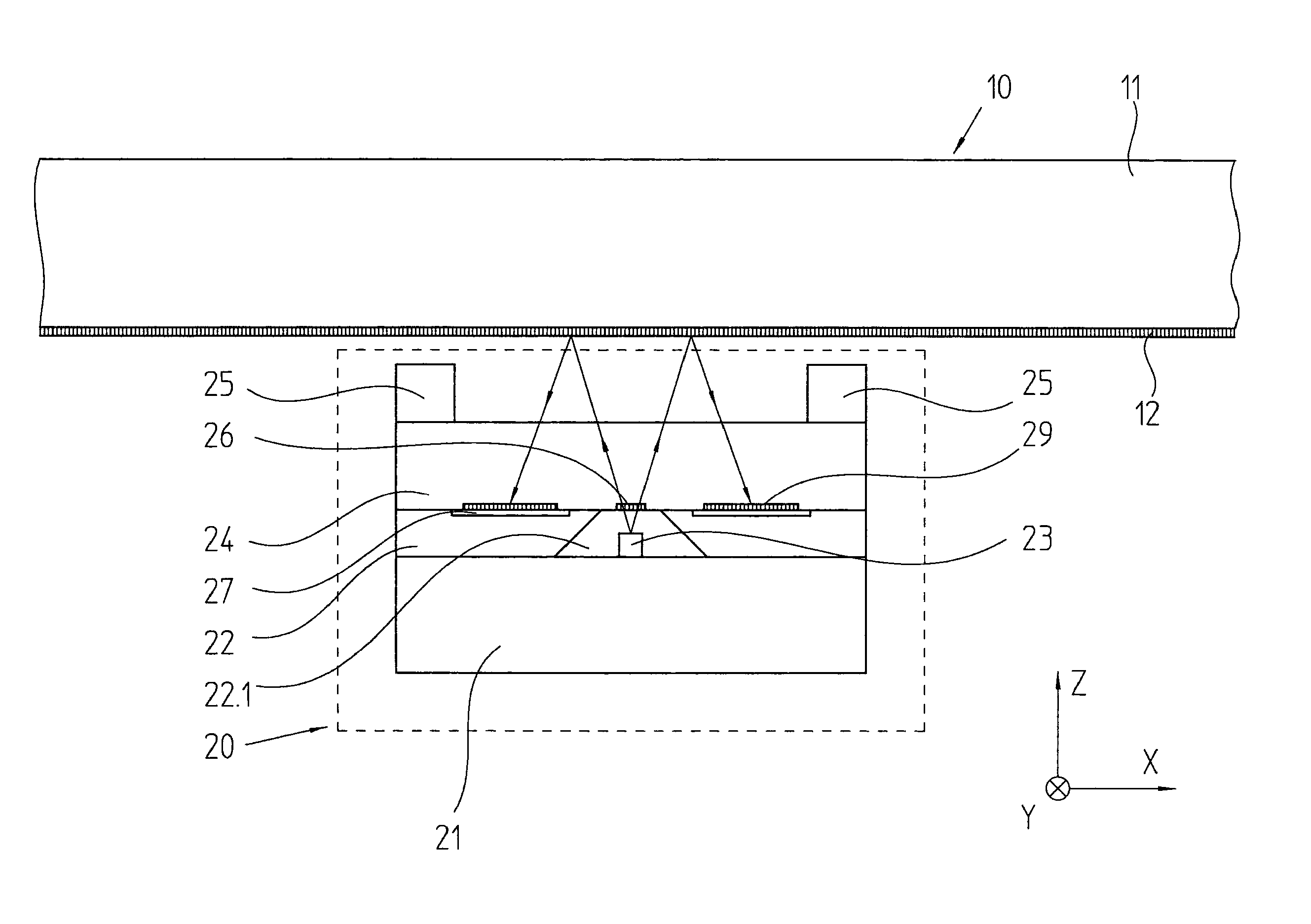
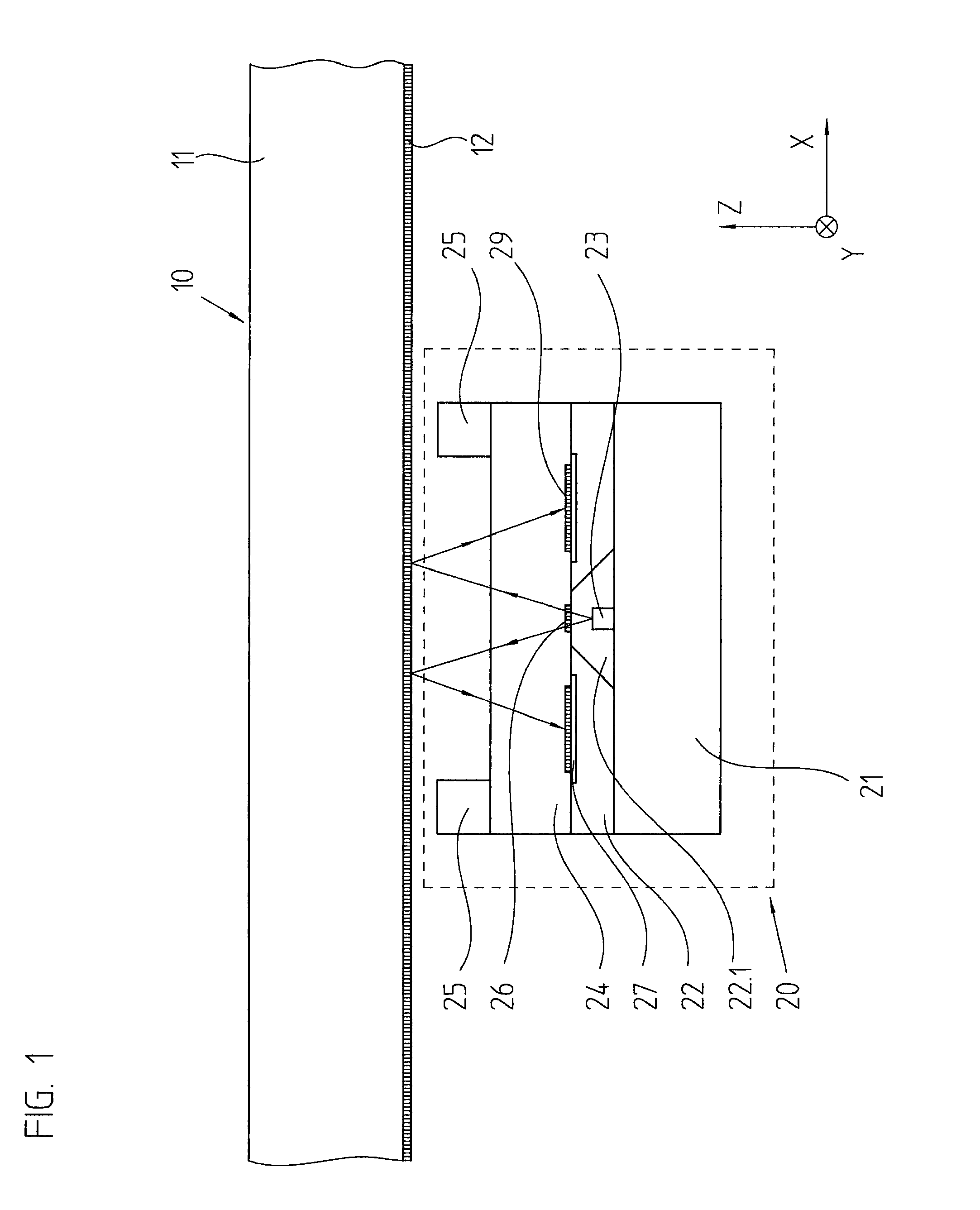
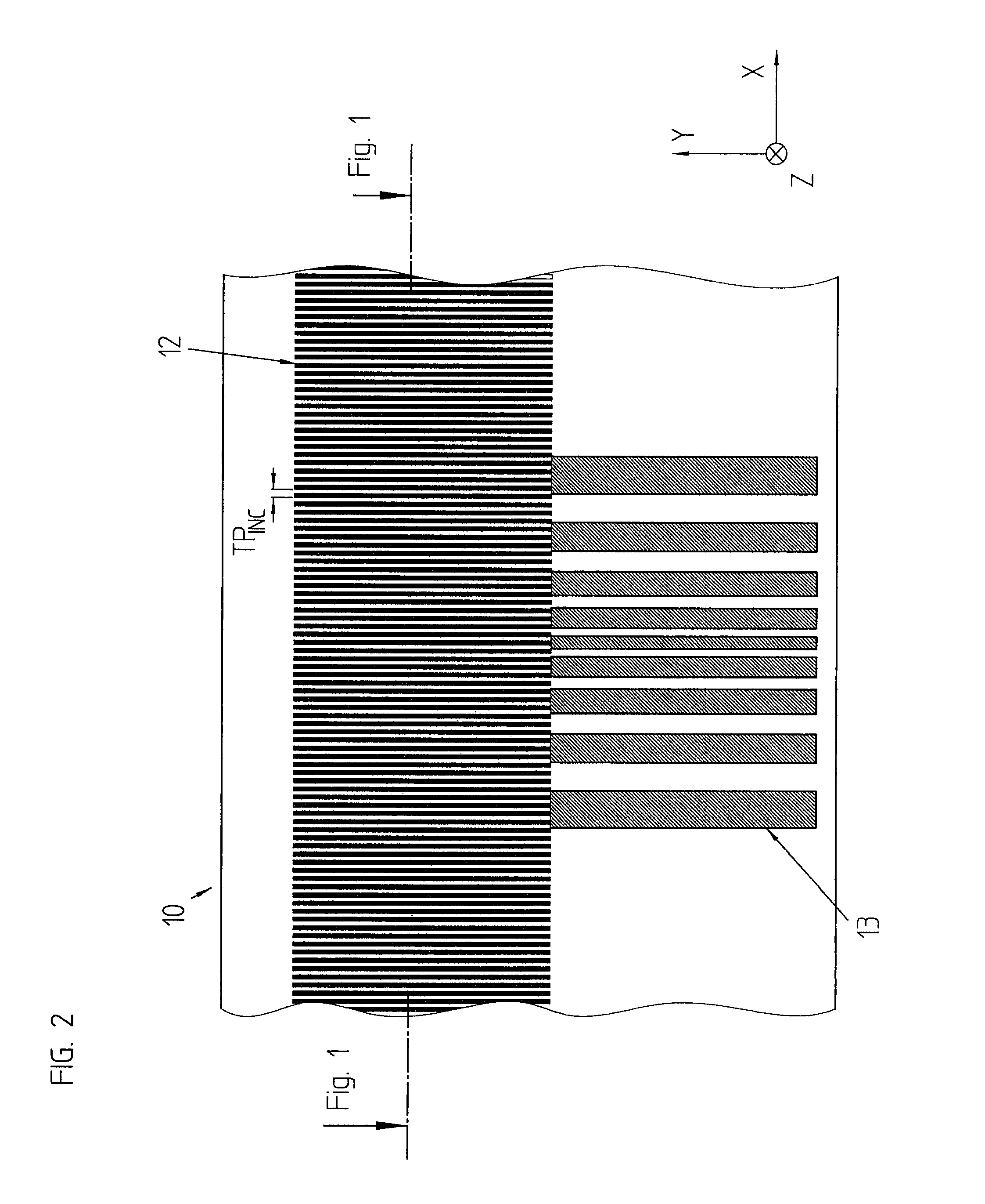
[0033]FIGS. 1 to 3 schematically illustrate an optical position-measuring device according to an example embodiment of the present invention, the device being configured as a reflective light system. FIG. 1 is a lateral cross-sectional view, FIG. 2 is a plan view of the measuring standard, and FIG. 3 is a plan view of the detection plane in the scanning unit.

[0034]The optical position-measuring device for detecting the position of two objects that are movable relative to each other along at least one measuring direction x includes a measuring standard 10 and a scanning unit 20. Measuring standard 10 and scanning unit 20 are connected to the two objects, which are not shown in the figures. For instance, these objects may be machine components that are movable relative to each other. If the machine components move with respect to each other, the optical position-measuring device generates positional signals, which are processed by a downstream machine control.

[0035]The Figures shows a...


PUM


Abstract

An optical position-measuring device for detecting the relative position of two objects includes a measuring standard connected to one object, and a scanning unit connected to the other object and including a light source, one or more grating(s), and a detector system. The detector system includes a plurality of detector element groups arranged in a detection plane, via which a plurality of position-dependent, phase-shifted scanning signals is able to be generated by scanning a periodic fringe pattern that results in the detection plane, the detector elements that have in-phase scanning signals forming a group in each case. The sum of the areas and the centroid of the detector elements of a group is identical to the sum of the areas and the centroid, respectively, of the detector elements of each other group. Periodic diaphragm structures are arranged in front of the light-sensitive areas of the detector elements.

Description

CROSS-REFERENCE TO RELATED APPLICATIONS[0001]The present application claims priority to Application No. 10 2011 075 286.2, filed in the Federal Republic of Germany on May 5, 2011, which is expressly incorporated herein in its entirety by reference thereto.FIELD OF THE INVENTION[0002]The present invention relates to an optical position-measuring device.BACKGROUND INFORMATION[0003]Conventional position-measuring devices for measuring the position of two objects that are movable relative to each other along at least one measuring direction are made up of a measuring standard which is connected to one of the two objects, as well as a scanning unit which is connected to the other one of the two objects. The measuring standard includes an incremental graduation which extends in the measuring direction. The scanning unit has a light source, one or more grating(s), as well as a detector system. A plurality of groups of detector elements, which are disposed in a detection plane, is provided ...

Claims


Application Information

Patent Timeline
Patent Type & Authority Patents(United States)
IPC IPC(8): G01B11/02G01D5/347
CPCG01D5/34715
Inventor HERMANN, MICHAEL
Owner DR JOHANNES HEIDENHAIN GMBH
Why Eureka
Try Eureka