
Multi-terminal power conversion device, multi-terminal power transfer device, and power network system

a power network and multi-terminal technology, applied in the direction of electric variable regulation, process and machine control, instruments, etc., can solve the problems of affecting the synchronization capability of the existing grid, the tendency of sources to impair the frequency stability of the system, and the inability of power generation and wind power generation to provide synchronizing power, etc., to achieve flexible power exchange and reduce the capacity of interconnection devices and network connections

Active Publication Date: 2015-04-21
THE UNIV OF TOKYO
View PDF25 Cites 16 Cited by
  • Summary
  • Abstract
  • Description
  • Claims
  • Application Information

AI Technical Summary

Benefits of technology

[0049]If a plurality of power grids are connected together by an asynchronous interconnection multi-terminal power conversion device as in the present invention, then first, a large number of interconnection networks are created which complement one another in supplying power required to allow each power grid to operate autonomously, thus significantly reducing the capacities of interconnection devices and network connections. Hence, the amount of interchangeable power increases consistently with the number of inter-power grid networks, thus allowing a proportional increase in the amount of renewable energy power introduced into the power grids. A bulk power grid can avoid dealing with the fluctuations in renewable energy power. This eliminates the need to provide an excess of interconnection capacity, and enables conventional high-quality power grids to be maintained.
[0050]Second, the power network system resulting from the present invention enables power to be interchanged among any particular power apparatuses or power grids. For the power interchange, a power interchange procedure is established based on transaction requirements. The addition of information with the interchangeable power enables more flexible power interchange and enables the recording of power transactions.
[0051]Third, each power grid can operate autonomously without an excessively large power generation facility or storage device, through interconnection with a network with other power grids or with a bulk power grid. Thus, renewable energy power that is advantageous for the local district can be freely loaded into the power grid. The results of Japan's New Energy and Industrial Technology Development Organization (NEDO) investigations show that even solar power generation alone could provide energy in the amount of which is nearly 1,000 times as large as that consumed by human beings annually and that if solar panels are laid in districts in Japan where solar power generation has not been utilized yet, the amount of generated power would be about eight times as large as that consumed. The present invention significantly contributes to introduction of such a large amount of renewable energy.

Problems solved by technology

This limitation is because renewable energy power sources such as solar power generation and wind power generation cannot provide synchronizing power.
The power sources thus have the tendency of impairing the frequency stability of the system by magnifying normal power fluctuations.
Thus, the introduction of large amounts of renewable power that fluctuates severely impairs the synchronization capability of the existing grid.
This may lead to a catastrophe such as cascading massive power failure.
However, the conventional art includes no document or report regarding such a system or procedure.

Method used


Image

  • Multi-terminal power conversion device, multi-terminal power transfer device, and power network system
  • Multi-terminal power conversion device, multi-terminal power transfer device, and power network system
  • Multi-terminal power conversion device, multi-terminal power transfer device, and power network system

Examples


Embodiment Construction

[0103]First, the difference between power interchange in a conventional AC synchronous grid and power interchange based on power conversion that is the basic principle of the present invention will be described.

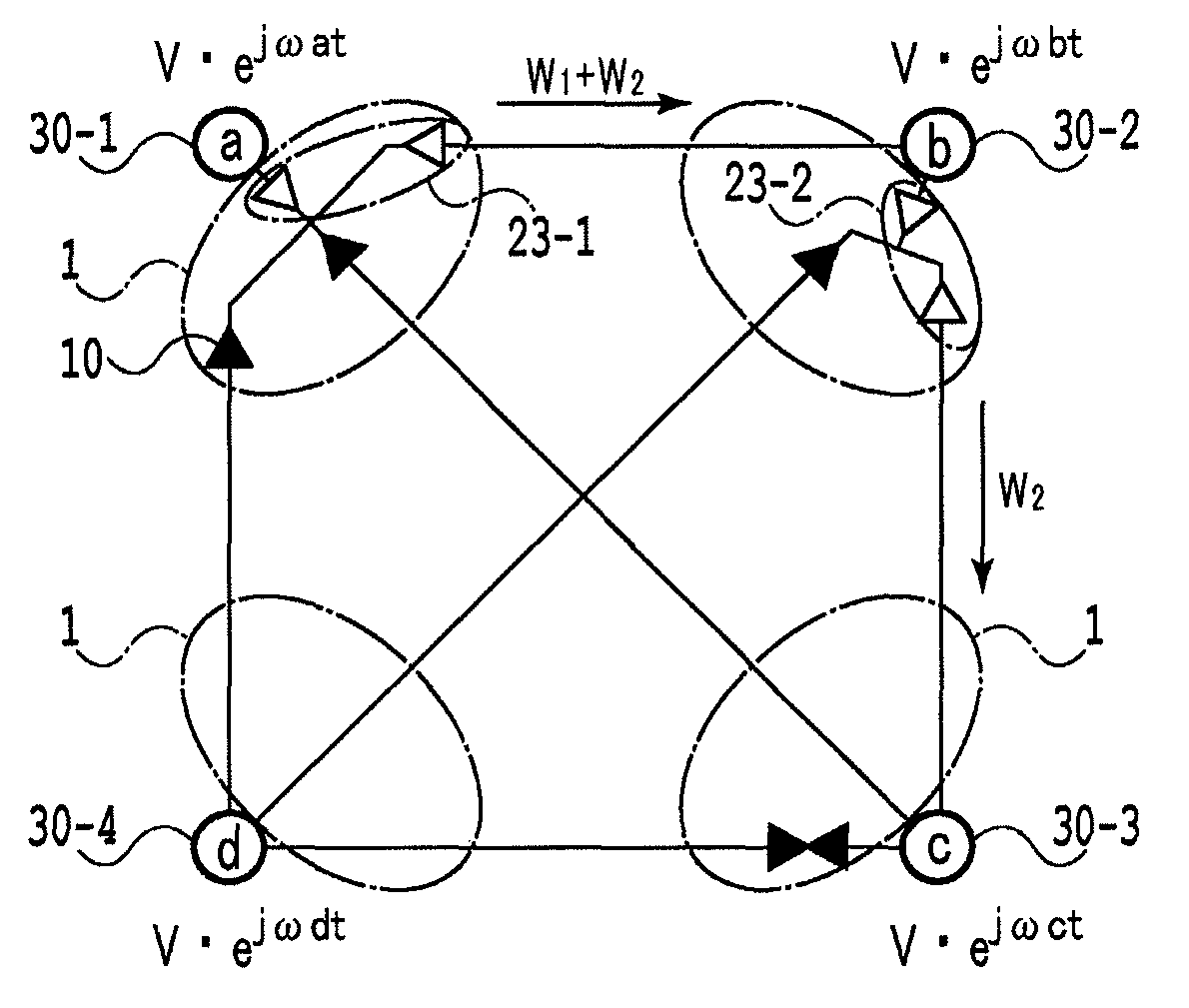
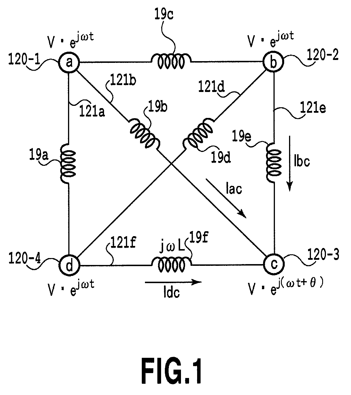
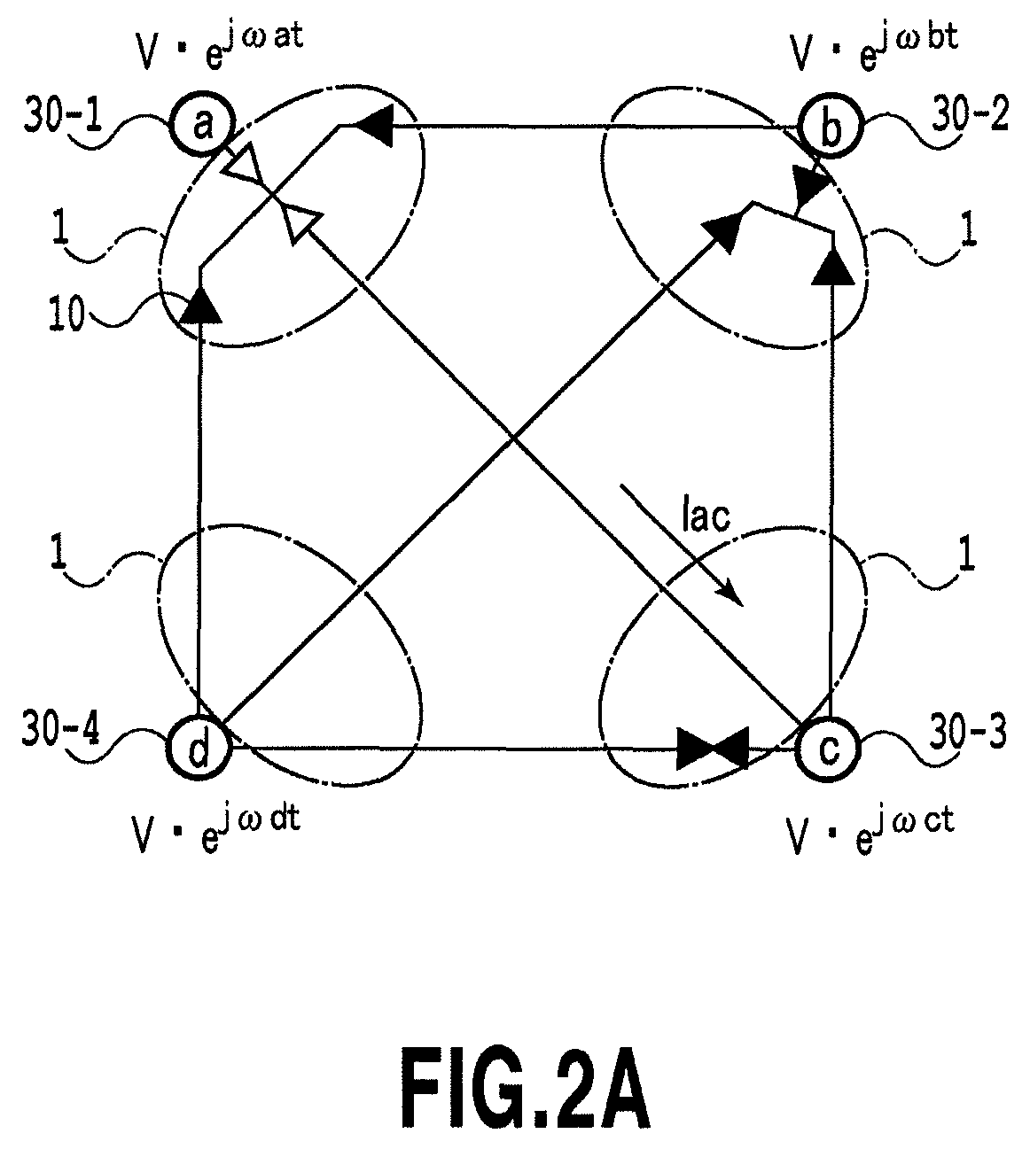
[0104]FIG. 1 shows a conventional AC synchronous grid in which four power grids (nodes 120-1 to 120-4) are connected together by six interconnecting electric lines (links 121-1 to 121-4). Each of the interconnecting electric lines has a reactor component 19 with a line of inductance L. FIG. 2A shows an AC asynchronous grid according to the present invention in which four nodes (nodes 30-1 to 30-4) are connected together by six links via A connection terminals and B connection terminals of multi-terminal power conversion devices 1. For simplification, AC filters, connection reactors and transformers are omitted from the figures.

[0105]In an initial condition of a circuit network in FIG. 1, the four nodes are synchronized at a voltage V, a phase of 0, and a frequency ω / 2π. In th...


PUM


Abstract

The present invention provides a multi-terminal power conversion device, a multi-terminal power transfer device, and a power network system which allows an existing power grid to be divided into a plurality of power grids that can be interconnected together and operated stably via existing or new transmission lines. An inter-power grid asynchronous interconnection network system includes a multi-terminal power conversion device characterized by connecting together a plurality of asynchronous power grids including a bulk power grid and controlling power so that the sum of inflow power and outflow power is zero. An intra-power grid synchronous network system includes a power apparatus control terminal device with means for controlling power for a power apparatus installed in an autonomous power grid. A plurality of inter-power grid asynchronous interconnection network systems are connected to an intra-power grid synchronous network system to integrate the power control with communication control.

Description

TECHNICAL FIELD[0001]The present invention relates to a multi-terminal power conversion device, a multi-terminal power transfer device, and a power network system, and in particular, to a multi-terminal power conversion device, a multi-terminal power transfer device, and a power network system which allow a plurality of power grids to be asynchronously connected together via a multi-terminal power conversion device and a multi-terminal power transfer device both installed at each of the power grids, thus enabling specified power to be interchanged among specified power grids for a specified time.BACKGROUND ART[0002]Electric power is mostly supplied by power grids of a power company through a transmission network of a bulk power grid. The frequency of a power grid results from the balance between demand (load) and supply (generated output). Thus, the power company matches the supply and demand on a moment-by-moment basis by controlling load fluctuation of at most several tens of seco...

Claims


Application Information

Patent Timeline
Patent Type & Authority Patents(United States)
IPC IPC(8): G06F19/00H02J3/00H02M1/00H02M5/45
CPCH02J3/00H02M5/4505H02M2001/008Y10T307/406H02M1/008
Inventor ABE, RIKIYA
Owner THE UNIV OF TOKYO
Learn More