Mobility device

a mobility device and a technology for carrying people, applied in the direction of wheelchairs/patient conveyances, wheelchairs/perambulators with multiple axes, movable seats, etc., can solve the problems of more difficult conventional scooters or wheelchairs, and achieve the effect of preventing the movement of the mobility device, reducing long-term fatigue, and facilitating sitting for the occupan

Inactive Publication Date: 2015-04-28
RIDEUP MOBILITY
View PDF7 Cites 12 Cited by
  • Summary
  • Abstract
  • Description
  • Claims
  • Application Information

AI Technical Summary

Benefits of technology

[0009]The mobility device of the present invention is a device for an able body person, temporary disabled people or individuals that are experiencing need for a mobility aid. Multiple features make it more usable than a regular wheelchair or mobility device and give the occupant a chance to stay mobile for longer periods of time. The small size of the wheeled base gives the mobility device access to smaller areas, which is more difficult with conventional scooters or wheelchairs. The mobility device gives more independence with an active body posture for the occupant. The general geometry of the mobility device gives the occupant a dynamic position for a more reactive and interactive ride.
[0010]An important feature of the mobility device is the rear access to seating position. Rear access to the mobility device is made possible by opening outwardly and upwardly the side support structure, providing an access to the occupant. In preferred embodiment, both left and right side support structure pivot outwardly and upwardly simultaneously, i.e. at the same time. In another preferred embodiment, both left and right side support structure pivot outwardly and upwardly successively, this is achieved by providing a vertical pivoting mechanism and a lateral pivoting mechanism. The right and left side support structure, or lateral support structure, pivot outwardly, leaving the rear clear for an occupant to step onto the wheeled base and then to seat on the seat structure. The rear access enables the mobility device to be positioned adjacent to a bed so that the occupant does not need to turn 180 degrees before being seated. Also, the mobility device provides clearance to the toilet without the occupant needing to spin 180 degree. It is to be understood that the side support structure could also open only laterally along a vertical axis.
[0012]One of the goals of the present invention is to provide a lightweight, affordable, and compact mobility device that enables occupants to transport themselves. The mobility device can be used to move around all types of urban living environments. The mobility device is collapsible for convenient storage or transportation.
[0013]The mobility device of the present invention enables the occupant to transport and maneuver themselves to the wide variety of domestic and urban environments that can be faced on a daily basis, all the while maintaining a comfortable dynamic sitting position.
[0015]Locking motorized wheels prevent movement of the mobility device during mounting and dismounting, i.e. when the side support structure is in an opened configuration.
[0016]The position of an occupant in the mobility device is active or dynamic in the sense that the legs, the abdomen and back muscles are being used, unlike a conventional wheelchair where there is a static strain on the muscles that lead to discomfort. The dynamic position maintains the blood circulation and reduces the long-term fatigues. The present mobility device makes it easier for an occupant to sit with a balanced upper torso that maintains the natural curve of the back without a complete back support.

Problems solved by technology

The small size of the wheeled base gives the mobility device access to smaller areas, which is more difficult with conventional scooters or wheelchairs.

Method used


Image

  • Mobility device
  • Mobility device
  • Mobility device

Examples


Embodiment Construction

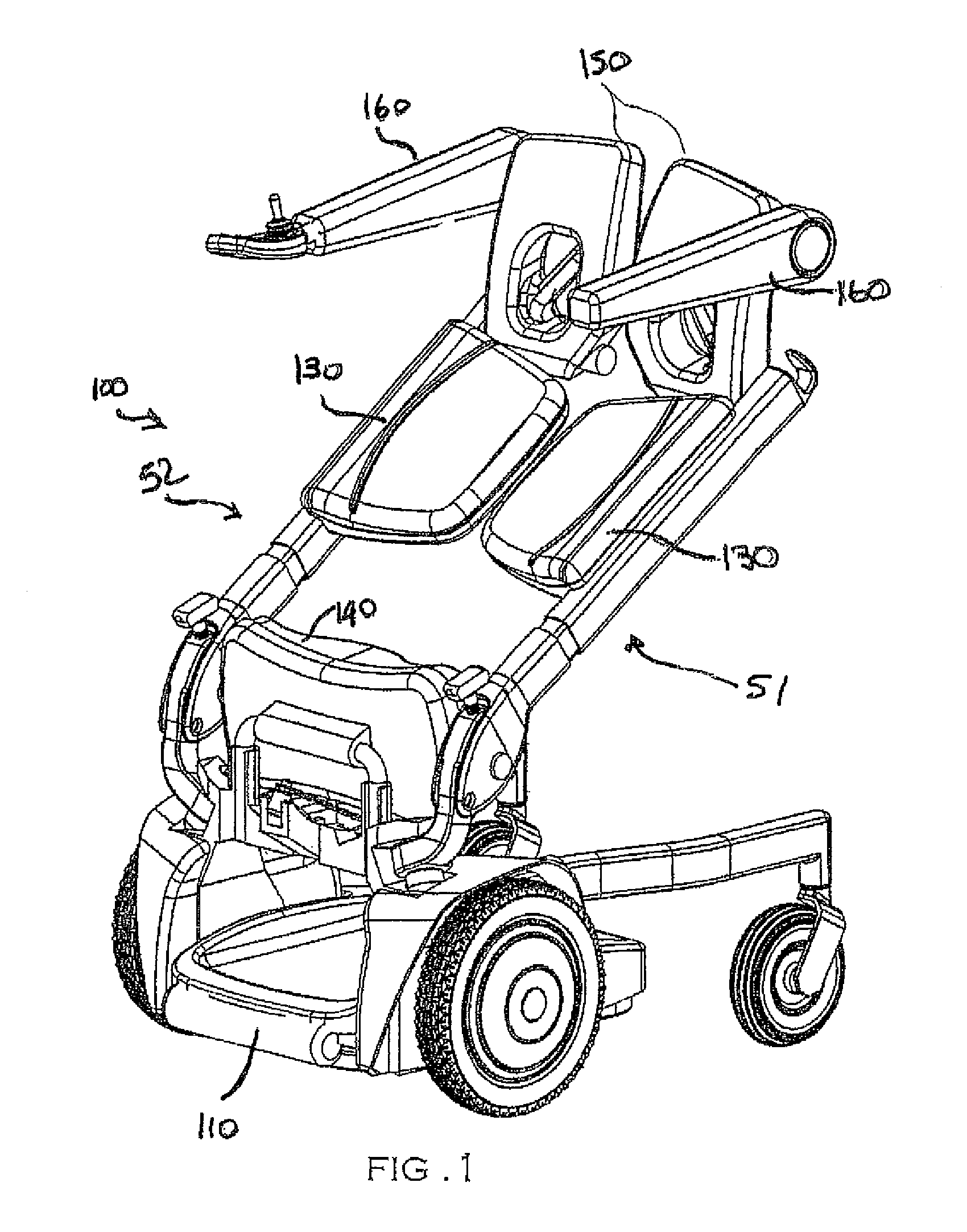
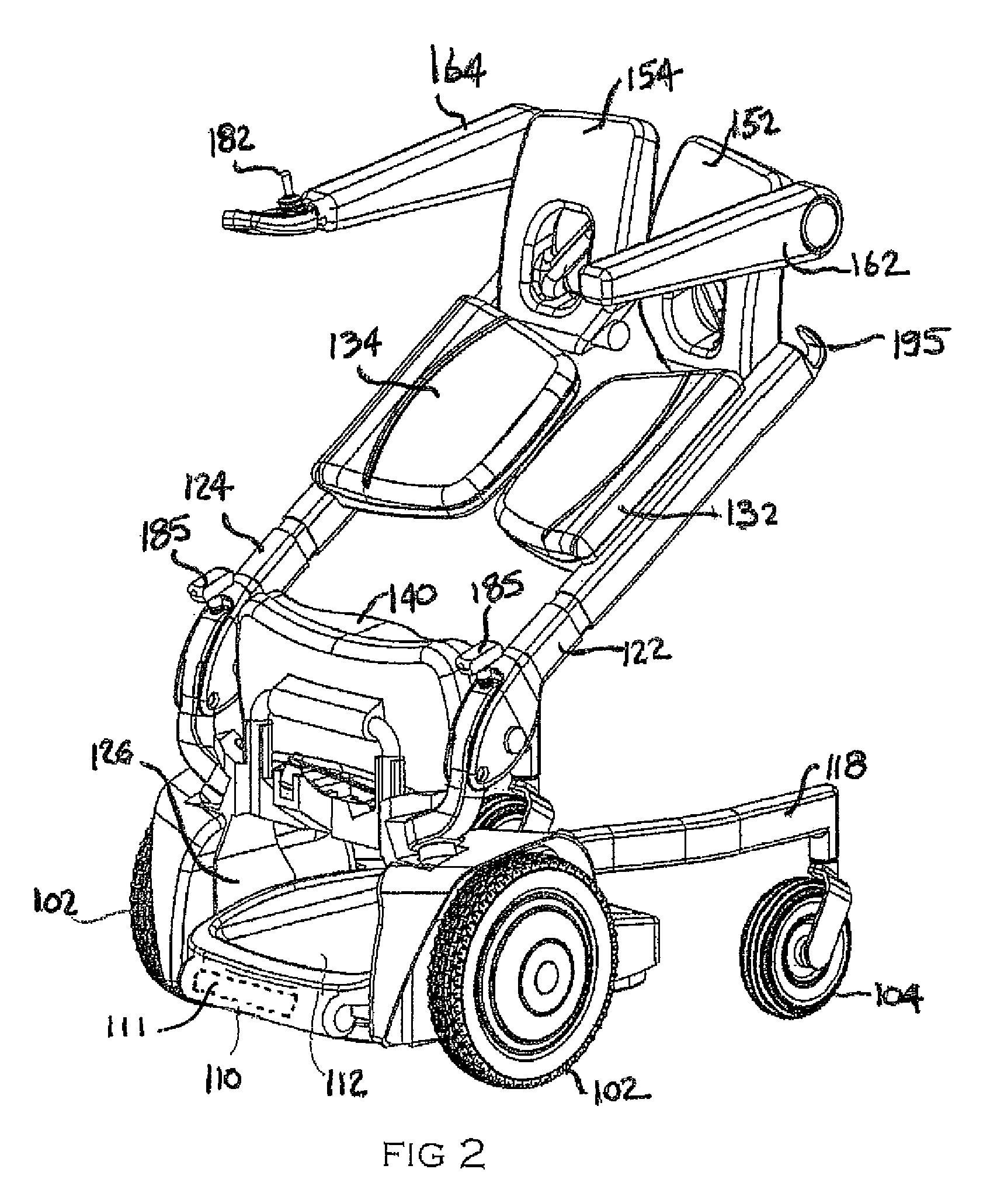
[0051]A novel mobility device will be described hereinafter. Although the invention is described in terms of specific illustrative embodiments, it is to be understood that the embodiments described herein are by way of example only and that the scope of the invention is not intended to be limited thereby.

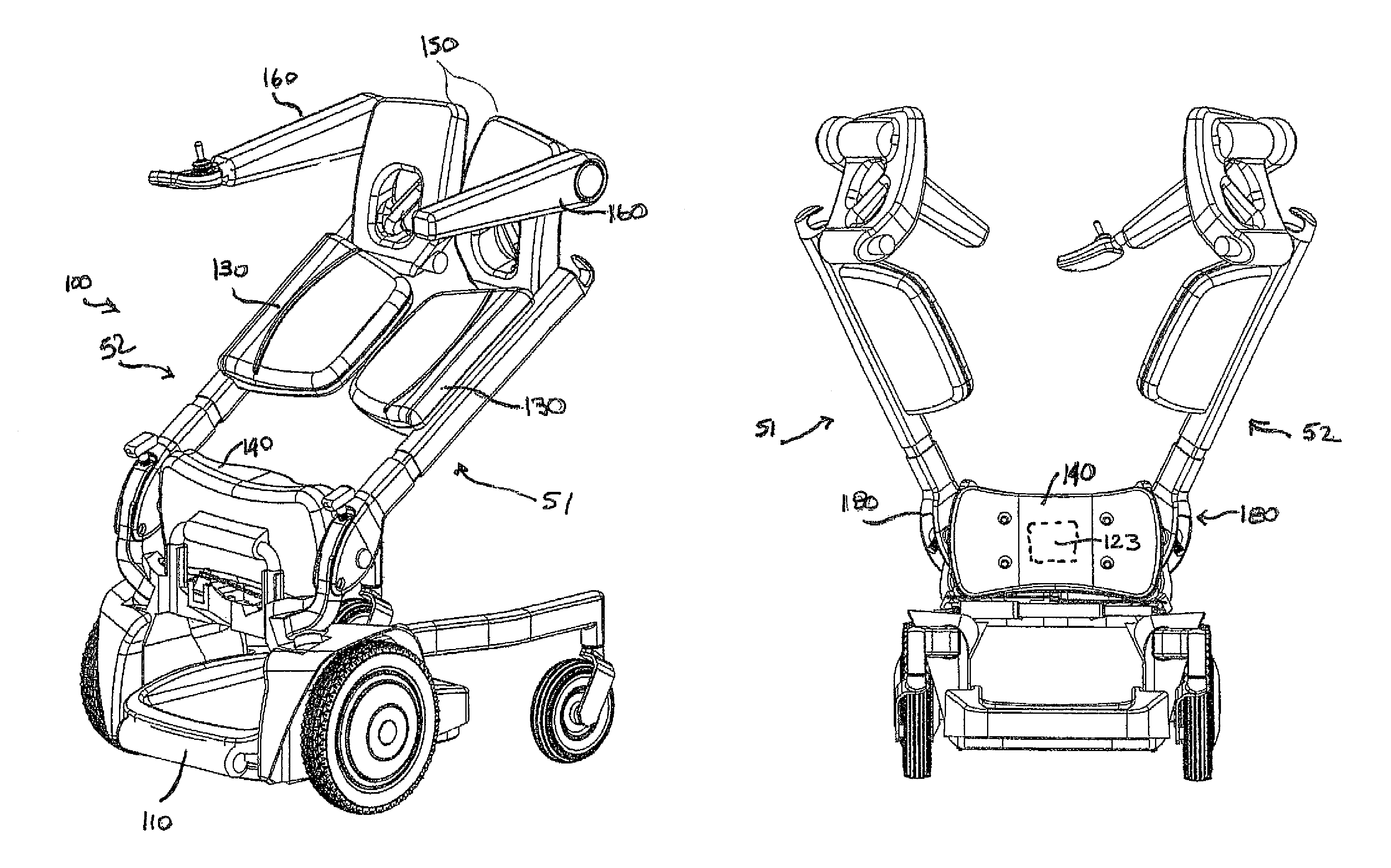
[0052]As illustrated in FIGS. 1 and 2, the mobility device 100 generally comprises a wheeled base 110, a seat structure 130, a shin rest structure 140, a back rest structure 150 and an arm rest structure 160.

[0053]The mobility device generally comprises a left side support structure 51 and a right side support structure 52 that may be opened outwardly to provide a rear access to the mobility device, allowing an occupant to sit down on the mobility device, as it will be explained hereafter, and to exit the mobility device easily. The height and general configuration of the mobility device can be adjusted for each occupant, for comfort or for a particular activity. The mobility device...


PUM


Abstract

A mobility device for people who need assisted mobility comprising side support structures for supporting the weight of an occupant in a semi seated position, a back rest structure, a shin rest structure and an arm rest structure. The mobility device of the present invention provides a rear access which is feasible by moving outwardly and upwardly the side support structures.

Description

CROSS-REFERENCE TO RELATED APPLICATIONS[0001]The present patent application claims the benefits of priority of commonly assigned U.S. Provisional Patent Application No. 61 / 349,416, entitled “Motorized Personal Mobility Carrier”, and filed at the United States Patent and Trademark Office on May 28, 2010.FIELD OF THE INVENTION[0002]The present invention generally relates to personal carrying vehicle.BACKGROUND OF THE INVENTION[0003]The use of wheelchairs including both powered and manually driven wheelchairs has been well known for a great number of years. Wheelchairs have been used to effect the transport of the injured, sick, aged or some combination thereof. Typically, known manually operated wheelchairs include two large rear wheels which can be grasped by an occupant and rotated to advance the chair. Known powered wheelchairs include a fairly complex drive system for driving the wheels of the wheelchair in response to operation of a set of hand controls or the like. Known powered...

Claims


Application Information

Patent Timeline
Patent Type & Authority Patents(United States)
IPC IPC(8): B62B7/06A61G5/08A61G5/04A61G5/10A61G5/12A61G5/14B60N2/02
CPCB60N2/02A61G5/042A61G5/1059A61G5/107A61G5/14A61G2005/085A61G2005/125A61G2005/127A61G2005/128Y10S180/907A61H3/04A61G2200/36A61G2200/38A61H2003/043A61H2201/0161A61H2201/0192A61H2201/1246A61H2201/1623A61H2201/163A61H2201/1633A61H2201/1635A61H2201/5023A61G5/085A61G5/125A61G5/127A61G5/128
Inventor MOLINER, MICHAEL
Owner RIDEUP MOBILITY
Why Eureka
Try Eureka