

Method and device for producing process vapor and boiler feed steam in a heatable reforming reactor for producing synthesis gas
a technology of heatable reforming reactor and process steam, which is applied in the direction of steam generation using hot heat carriers, sustainable manufacturing/processing, ignition automatic control, etc., can solve the problems of insufficient amount of steam obtained from process condensate, and insufficient steam for all applications. , to achieve the effect of improving the cost-effectiveness of steam generation and reducing dependency
- Summary
- Abstract
- Description
- Claims
- Application Information
AI Technical Summary
Benefits of technology
Problems solved by technology
Method used
Image

Examples
Embodiment Construction
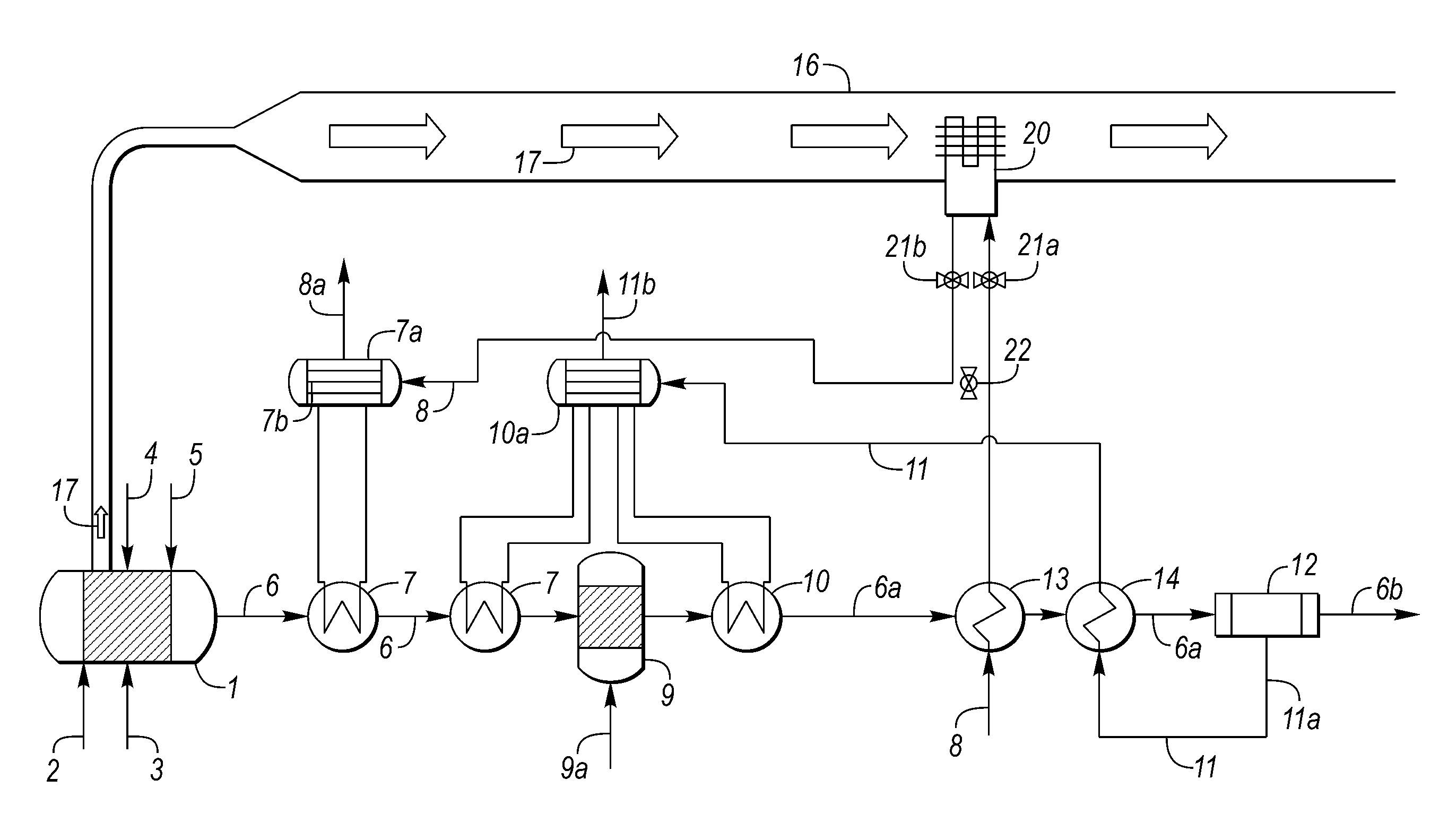
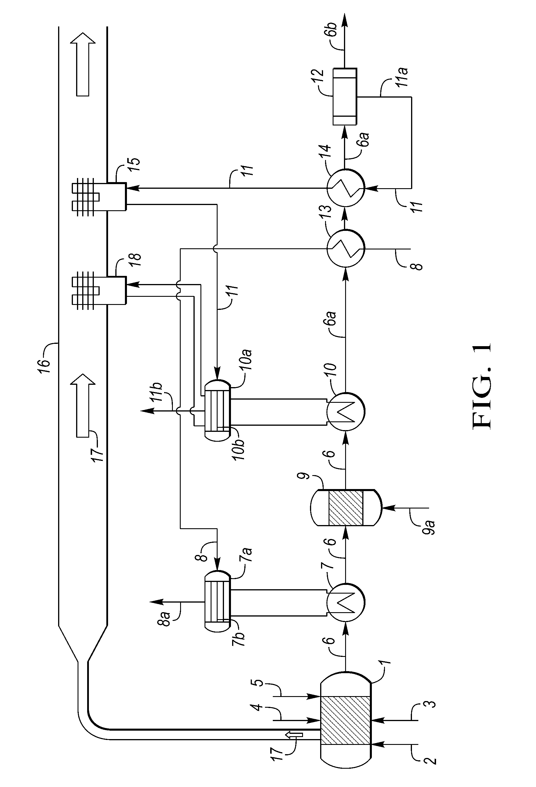
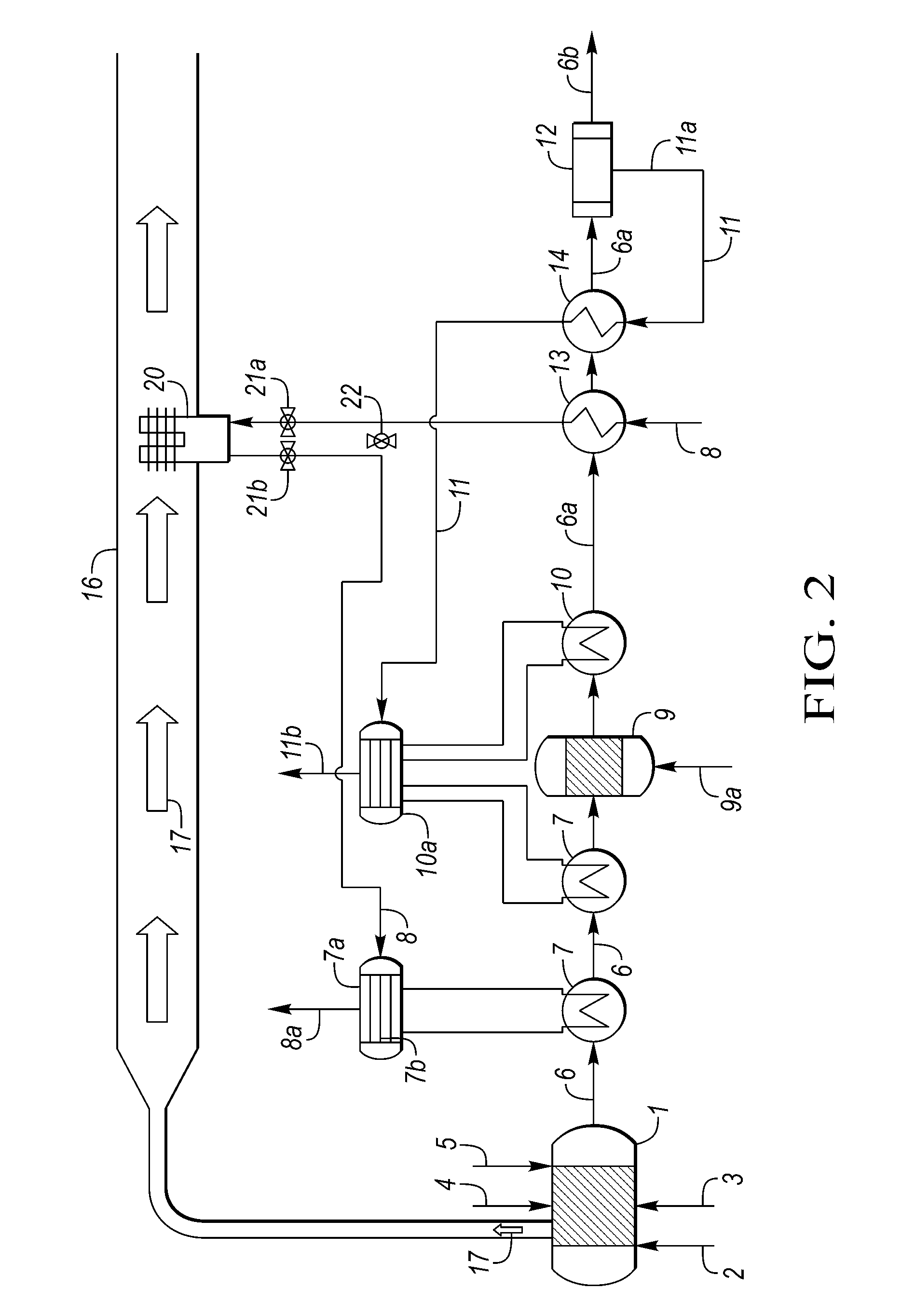
[0017]Cooling of the process gas from the reformer outlet to the inlet temperature of the water-gas shift reaction has up to now typically resulted in the evaporation of boiler feed water. Other examples show that part of the heat is also used for the pre-heating of feedstock. Thus the natural gas or the feed gas mixture, for example, can be used for the reforming reaction. Now, according to the present invention, process condensate is additionally evaporated between reformer outlet and inlet of the water-gas shift reaction. Thus it is advantageously achieved to evaporate process condensate by process gas. In this way it is possible to give up evaporation of the process condensate in the flue gas duct completely or in part. As the temperature difference between the process condensate and the hot syngas upstream of the CO conversion unit is relatively high, the heat exchanging surfaces required will be of significantly smaller size than in the flue gas duct. This will in turn contrib...
PUM
| Property | Measurement | Unit |
|---|---|---|
| temperature | aaaaa | aaaaa |
| corrosive | aaaaa | aaaaa |
| purity | aaaaa | aaaaa |
Abstract
Description
Claims
Application Information