
Inverter cover for motor-driven compressor

a technology for inverter covers and compressors, which is applied in the direction of positive displacement liquid engines, pumping, lighting and heating apparatus, etc., can solve the problems of increasing external electromagnetic noise can enter the inverter, and the metal plating cannot ensure the strength of the inverter case, so as to maintain the strength prevent external electromagnetic noise from flowing, and reduce the weight of the inverter cover

Active Publication Date: 2015-04-28
TOYOTA IND CORP
View PDF20 Cites 6 Cited by
  • Summary
  • Abstract
  • Description
  • Claims
  • Application Information

AI Technical Summary

Benefits of technology

The invention aims to create an electric compressor that has a stronger inverter cover while being lighter, and also stops external electromagnetic noise from getting inside the inverter.

Problems solved by technology

If made of metal, the inverter cover increases the weight of the electric compressor.
However, in the inverter case of the first prior art, external electromagnetic noise can intrude from the frame portion and flow into the inverter.
Also, in the inverter case of the second prior art, the metal plating cannot ensure the strength of the inverter case.
Further, due to changes in the temperature in the engine compartment, where the compressor is placed, the difference in the rate of the thermal expansion between the metal and the plastic can cause the metal plating to peel off the inverter case.
In such a case, the metal plating can no longer shield against external electromagnetic noise.
Also, a peeled flake of the metal plating can contact the inverter, causing short circuiting.

Method used


Image

  • Inverter cover for motor-driven compressor
  • Inverter cover for motor-driven compressor
  • Inverter cover for motor-driven compressor

Examples


Embodiment Construction

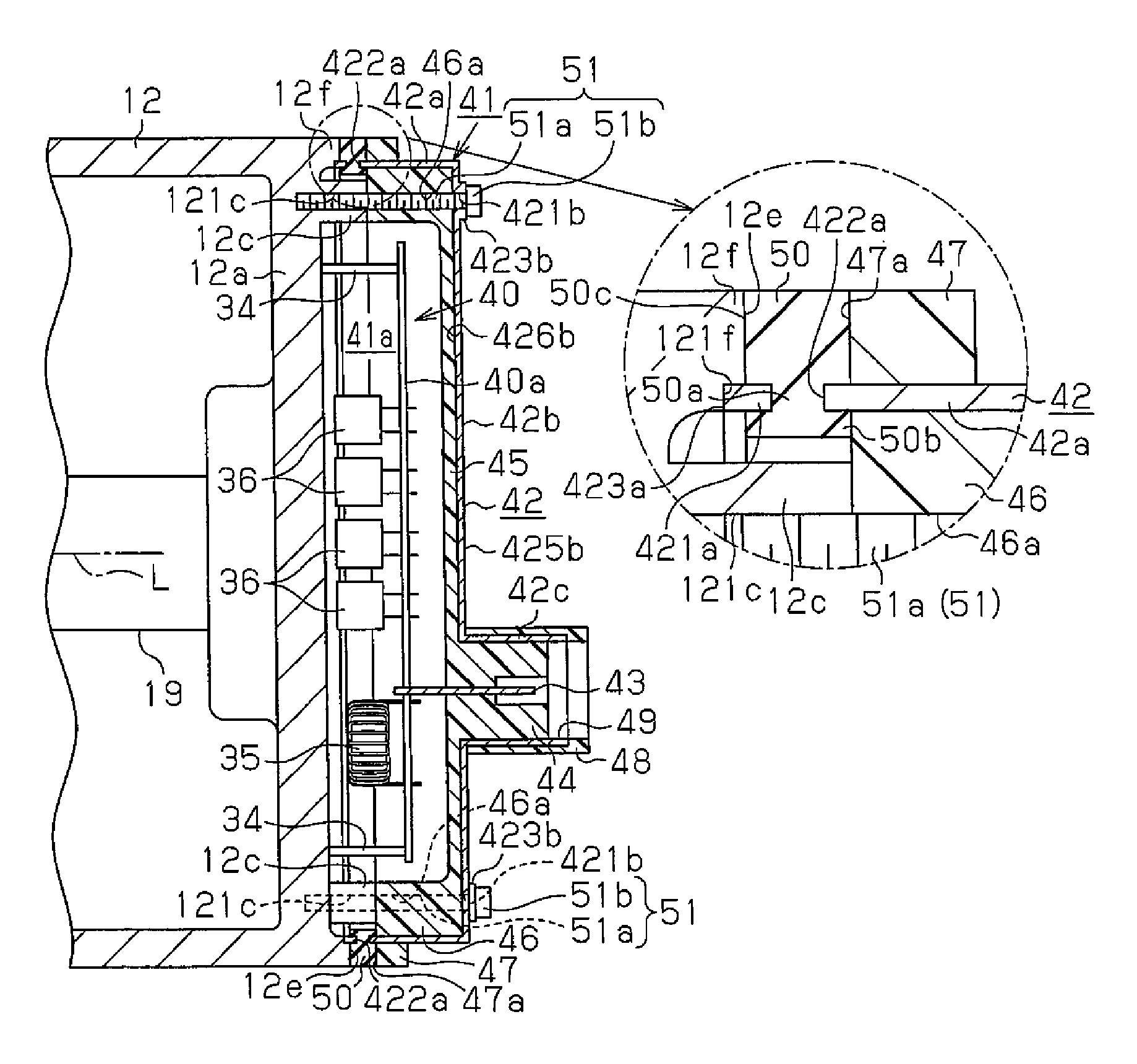
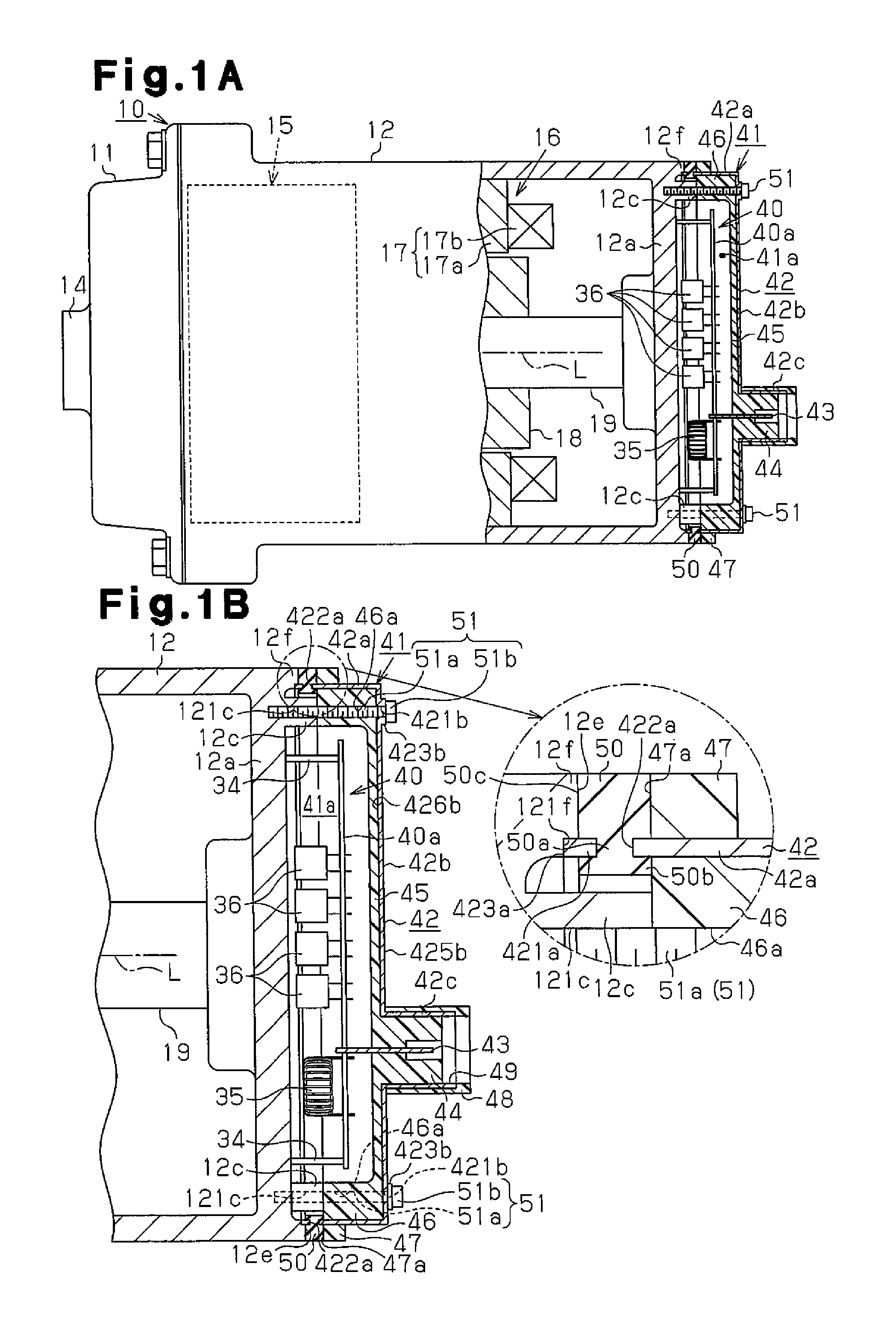
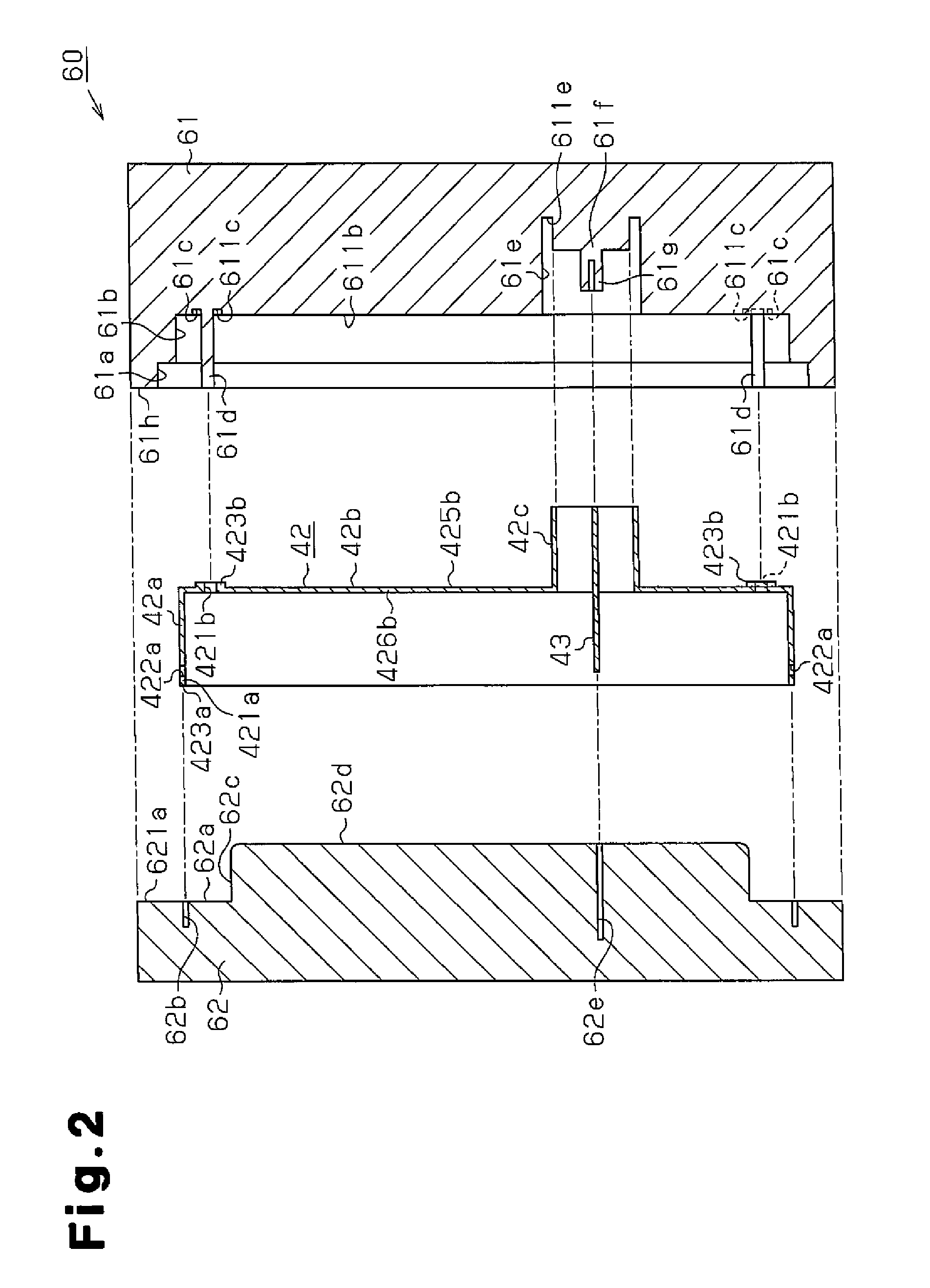
[0019]One embodiment of the present invention will now be described with reference to FIGS. 1A to 4.

[0020]As shown in FIG. 1A, a housing of an electric compressor 10 is formed by a discharge housing member 11 located on the left as viewed in FIG. 1A and a suction housing member 12 secured to the discharge housing member 11. The discharge housing member 11 and the suction housing member 12 are made of aluminum, that is, metal, and formed as a cylinder with one end closed. A suction port is formed in the bottom of the circumferential wall of the suction housing member 12. The suction port is connected to an external refrigerant circuit (not shown). A discharge port 14 is formed on the lid side, or the left side as viewed in FIG. 1A, of the discharge housing member 11. The discharge port 14 is connected to the external refrigerant circuit. The suction housing 12 accommodates a compressing portion 15 for compressing refrigerant (shown by a broken line in FIG. 1A) and an electric motor 1...


PUM


Abstract

An electric compressor includes an inverter cover. The inverter cover has a metal plate that is arranged to cover an inverter (a circuit board). The metal plate has bolt insertion holes, through which metal bolts for fixing the inverter cover to a suction housing are passed. The head of each bolt contacts a flange portion, which is the periphery of the corresponding bolt insertion hole. The inverter cover is formed of plastic by being molded in a mold, using the metal plate as a core.

Description

BACKGROUND OF THE INVENTION[0001]The present invention relates to an electric compressor.[0002]An electric compressor includes a compressing portion for compressing and discharging refrigerant, an electric motor for driving the compressing portion, and a housing for accommodating the compressing portion and the electric motor. An inverter cover, which accommodates an inverter for driving the electric motor, is fixed to the housing. If made of metal, the inverter cover increases the weight of the electric compressor. Thus, to minimize the increase in the weight of the electric compressor, the weight of the inverter cover may be reduced, for example, by making the inverter cover with plastic. For example, refer to Japanese Laid-Open Patent Publication No. 2004-162618 (a first prior art) and Japanese Laid-Open Patent Publication No. 2002-155862 (a second prior art).[0003]The electric compressor of the first prior art has an inverter case (inverter cover). The inverter case includes a b...

Claims


Application Information

Patent Timeline
Patent Type & Authority Patents(United States)
IPC IPC(8): F04B35/04F01C21/10F04B39/12F04C23/00
CPCF04C23/008F01C21/10F04B35/04F04B39/121F04C2240/808F05C2201/021F04B17/03F04B39/12
Inventor KINOSHITA, YUSUKEENAMI, SHINGOSUITOU, KEN
Owner TOYOTA IND CORP
Learn More