Power generating apparatus
a power-generating apparatus and power technology, applied in the direction of piezoelectric/electrostrictive/magnetostrictive devices, piezoelectric/electrostriction/magnetostriction machines, electrical apparatus, etc., can solve the problems of affecting the operation of the power-generating apparatus. , to achieve the effect of suppressing the amount of deformation of th
- Summary
- Abstract
- Description
- Claims
- Application Information
AI Technical Summary
Benefits of technology
Problems solved by technology
Method used
Image
Examples
embodiment
A. Embodiment
A-1. Structure of Power-Generating Apparatus
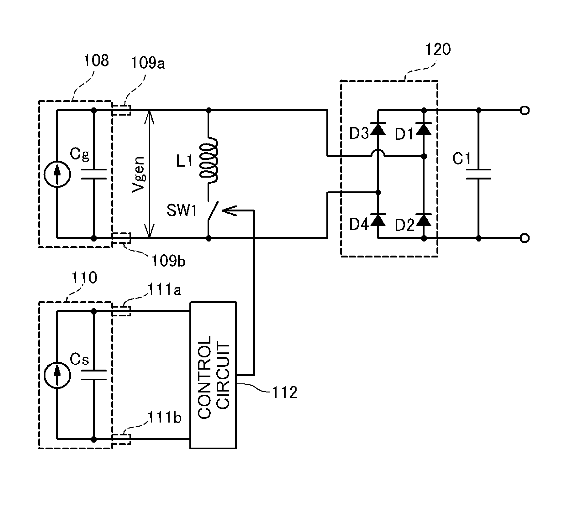
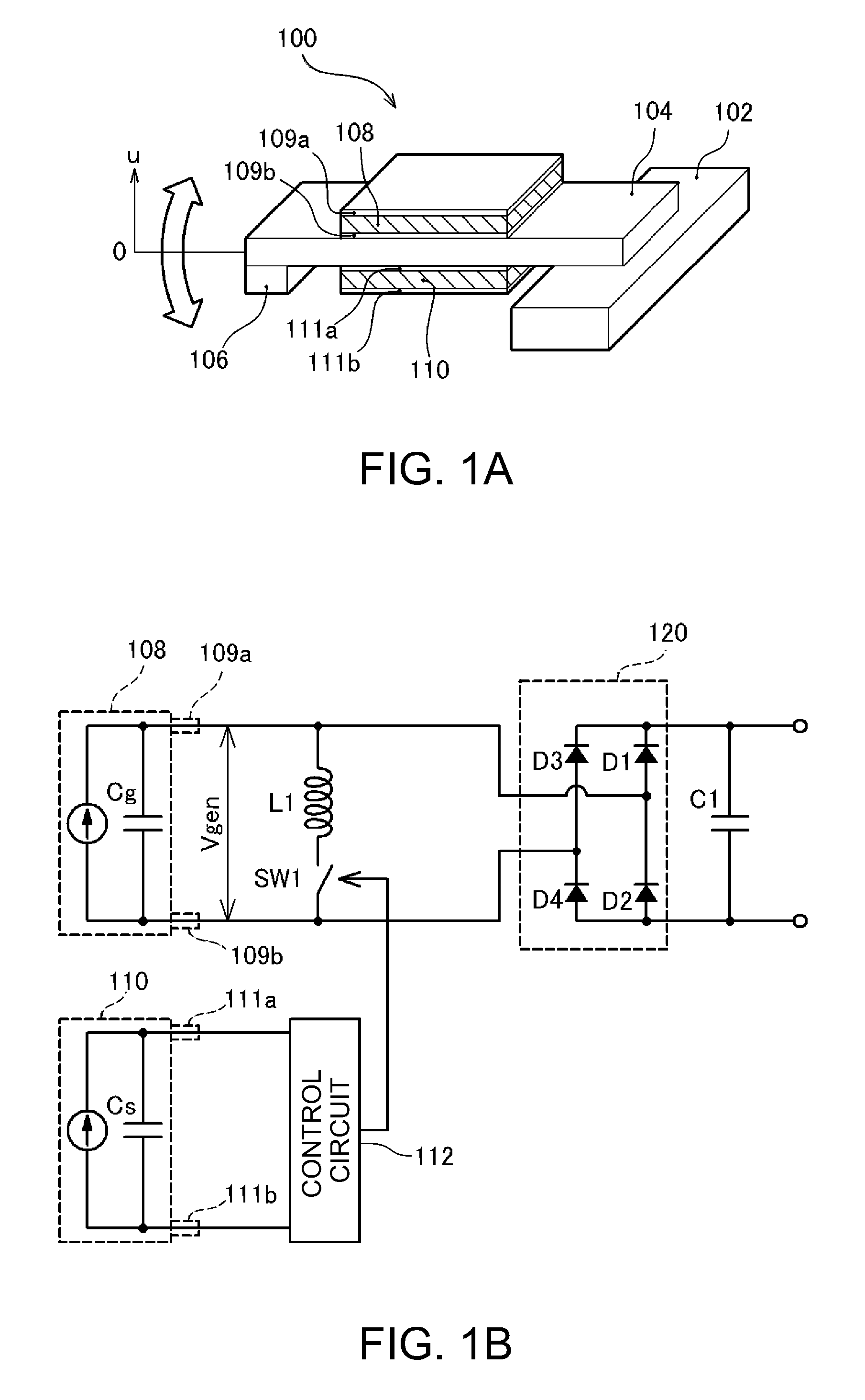
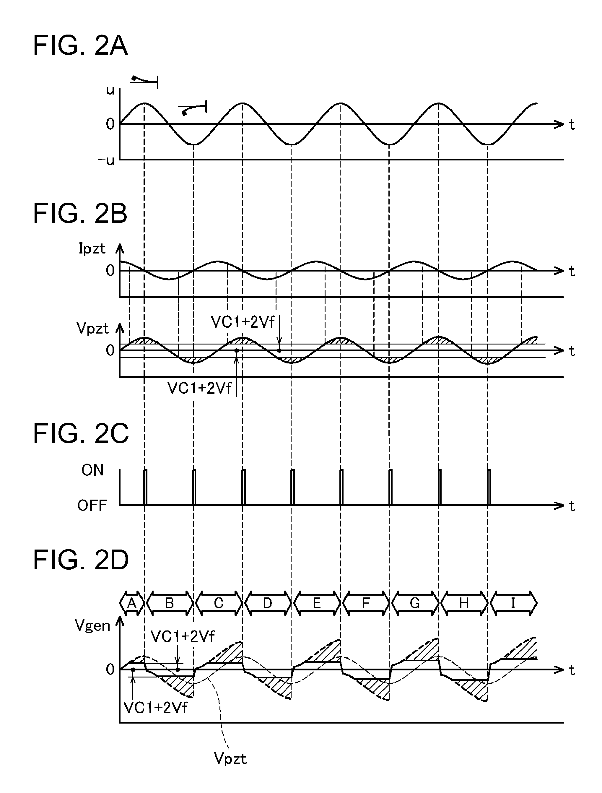
[0034]FIGS. 1A and 1B are explanatory diagrams showing a structure of a power-generating apparatus 100 of an embodiment. FIG. 1A shows the structure of the power-generating apparatus 100, and FIG. 1B shows a circuit diagram. The structure of the power-generating apparatus 100 of the embodiment is a cantilever structure in which a beam 104 provided with a weight 106 is fixed to a support end 102. Further, a piezoelectric device 108 and a piezoelectric device 110 formed by piezoelectric materials such as lead zirconate titanate (PZT) is attached to the surface of the beam 104, and an upper electrode 109a and a lower electrode 109b (a pair of electrodes) formed by metal thin films are provided on the surface of the piezoelectric device 108. Furthermore, similarly, on the piezoelectric device 110, an upper electrode 111a and a lower electrode 111b formed by metal thin films are provided. In the example shown in FIG. 1A, the piezoe...
first modified example
B. First Modified Example
[0075]There are various modified example of the above described embodiment. As below, the first modified example will briefly be explained.
[0076]In the power-generating apparatus 100 of the above described embodiment, one piezoelectric device 108 for power generation and one piezoelectric device 110 for control have been provided. However, these piezoelectric devices 108, 110 are not necessarily only ones, but pluralities of them may be provided. As below, the first modified example will be explained. Note that the same numbers are assigned to the same configurations as those of the above described embodiment in the modified example, and their detailed explanation will be omitted.
[0077]FIGS. 9A and 9B are explanatory diagrams showing power-generating apparatus 100A of the first modified example including pluralities of piezoelectric devices for power generation and piezoelectric devices for control. FIG. 9A is a plan view as seen from one surface of the beam...
second modified example
C. Second Modified Example
[0081]Next, a second modified example will briefly be explained.
[0082]FIG. 11 is an explanatory diagram showing an electric structure of a power-generating apparatus 100B of the second modified example. As clearly known from comparison between FIG. 11 and FIG. 1B, in the power-generating apparatus 100B of the second modified example, compared to the above described embodiment, the inductor L1 is not connected. That is, the LC resonance circuit like that in the above described embodiment is not formed within the power-generating apparatus 100B of the second modified example. Thereby, control processing (S100 to S108 in FIG. 8) for using the LC resonance circuit executed by the CPU built in the control circuit 112 may be omitted.
[0083]Obviously, the power-generating apparatus 100B of the second modified example does not use the LC resonance circuit unlike the power-generating apparatus 100 of the above described embodiment and the more effective accumulation ...
PUM
 Abstract
Description
Claims
Application Information
 - R&D
- Intellectual Property
- Life Sciences
- Materials
- Tech Scout
- Unparalleled Data Quality
- Higher Quality Content
- 60% Fewer Hallucinations
Browse by: Latest US Patents, China's latest patents, Technical Efficacy Thesaurus, Application Domain, Technology Topic, Popular Technical Reports.
© 2025 PatSnap. All rights reserved.Legal|Privacy policy|Modern Slavery Act Transparency Statement|Sitemap|About US| Contact US: help@patsnap.com


