Power-generating apparatus

a power-generating apparatus and power-generating technology, applied in the direction of piezoelectric/electrostrictive/magnetostrictive devices, piezoelectric/electrostriction/magnetostriction machines, electrical apparatus, etc., can solve the problems of affecting the operation of the power-generating apparatus. , to achieve the effect of suppressing the amount of deformation

Active Publication Date: 2012-08-23
SEIKO EPSON CORP
View PDF7 Cites 22 Cited by
  • Summary
  • Abstract
  • Description
  • Claims
  • Application Information

AI Technical Summary

Benefits of technology

[0007]An advantage of some aspects of the invention is to provide a technology that can preferably downsize a power-generating apparatus containing a cantilever by suppressing excessive vibration of the cantilever.
[0011]According to the configuration, since the second piezoelectric device is provided on the deformation member, the second piezoelectric device is also deformed according to the deformation of the deformation member. That is, in the second piezoelectric device, the voltage in response to the amount of deformation of the deformation member is generated. Therefore, the amount of deformation of the deformation member can be detected based on the voltage generated in the second piezoelectric device. The second piezoelectric device may be provided at the same step as the step of providing the first piezoelectric device, and thus, productivity can be improved.

Problems solved by technology

In a power-generating apparatus using the technology, when a force beyond the scope of the assumption acts on the cantilever and the cantilever excessively vibrates, the cantilever may collide with a surrounding member and break.
However, there has been a problem that it is difficult to sufficiently downsize the power-generating apparatus because it is necessary to secure a space for providing the elastic body in the proposed technologies in related art.
Further, when the amount of deformation is equal to or more than the predetermined amount, short-circuit is caused between the pair of electrodes provided in the first piezoelectric device.

Method used


Image

  • Power-generating apparatus
  • Power-generating apparatus
  • Power-generating apparatus

Examples


embodiment

A. Embodiment

A-1. Structure of Power-Generating Apparatus

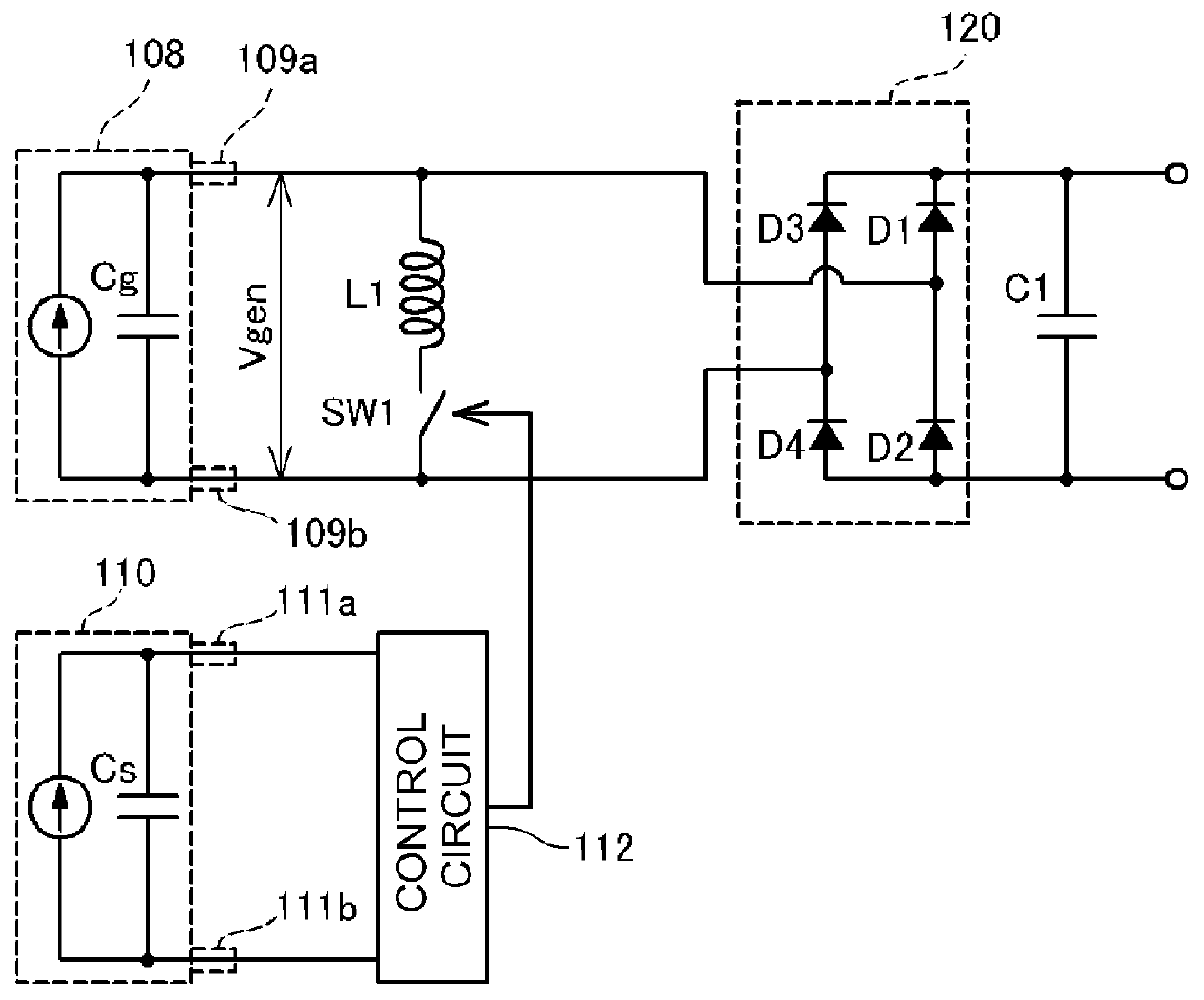
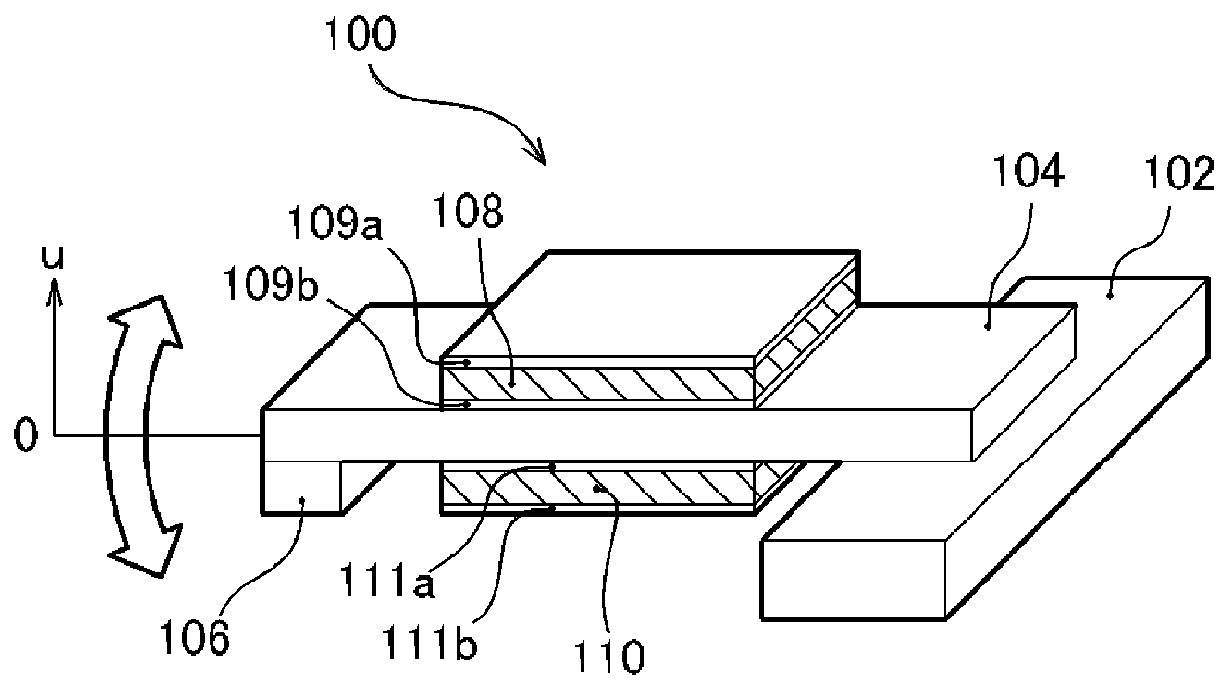
[0034]FIGS. 1A and 1B are explanatory diagrams showing a structure of a power-generating apparatus 100 of an embodiment. FIG. 1A shows the structure of the power-generating apparatus 100, and FIG. 1B shows a circuit diagram. The structure of the power-generating apparatus 100 of the embodiment is a cantilever structure in which a beam 104 provided with a weight 106 is fixed to a support end 102. Further, a piezoelectric device 108 and a piezoelectric device 110 formed by piezoelectric materials such as lead zirconate titanate (PZT) is attached to the surface of the beam 104, and an upper electrode 109a and a lower electrode 109b (a pair of electrodes) formed by metal thin films are provided on the surface of the piezoelectric device 108. Furthermore, similarly, on the piezoelectric device 110, an upper electrode 111a and a lower electrode 111b formed by metal thin films are provided. In the example shown in FIG. 1A, the piezoe...

first modified example

B. First Modified Example

[0075]There are various modified example of the above described embodiment. As below, the first modified example will briefly be explained.

[0076]In the power-generating apparatus 100 of the above described embodiment, one piezoelectric device 108 for power generation and one piezoelectric device 110 for control have been provided. However, these piezoelectric devices 108, 110 are not necessarily only ones, but pluralities of them may be provided. As below, the first modified example will be explained. Note that the same numbers are assigned to the same configurations as those of the above described embodiment in the modified example, and their detailed explanation will be omitted.

[0077]FIGS. 9A and 9B are explanatory diagrams showing power-generating apparatus 100A of the first modified example including pluralities of piezoelectric devices for power generation and piezoelectric devices for control. FIG. 9A is a plan view as seen from one surface of the beam...

second modified example

C. Second Modified Example

[0081]Next, a second modified example will briefly be explained.

[0082]FIG. 11 is an explanatory diagram showing an electric structure of a power-generating apparatus 100B of the second modified example. As clearly known from comparison between FIG. 11 and FIG. 1B, in the power-generating apparatus 100B of the second modified example, compared to the above described embodiment, the inductor L1 is not connected. That is, the LC resonance circuit like that in the above described embodiment is not formed within the power-generating apparatus 100B of the second modified example. Thereby, control processing (S100 to S108 in FIG. 8) for using the LC resonance circuit executed by the CPU built in the control circuit 112 may be omitted.

[0083]Obviously, the power-generating apparatus 100B of the second modified example does not use the LC resonance circuit unlike the power-generating apparatus 100 of the above described embodiment and the more effective accumulation ...


PUM


Abstract

A power-generating apparatus includes: a deformation member that is provided with a first piezoelectric device and deformed while switching a deformation direction; an amount of deformation detection unit that detects an amount of deformation of the deformation member; a pair of electrodes provided on the first piezoelectric device; a switch provided between the pair of electrodes; and a switch control unit that controls the switch to cause short-circuit between the pair of electrodes for a predetermined period when the amount of deformation is equal to or more than a predetermined amount.

Description

BACKGROUND[0001]1. Technical Field[0002]The present invention relates to a power-generating apparatus that extracts electric charge generated when a piezoelectric material such as a piezoelectric device is deformed by external forces as an electric energy.[0003]2. Related Art[0004]When a piezoelectric material such as lead zirconate titanate (PZT), crystal (SiO2), or zinc oxide (ZnO) is deformed by external forces, electric polarization is induced within the material and positive and negative electric charge appears on the surface. This phenomenon is the so-called piezoelectric effect. A power-generating method of vibrating a cantilever and repeatedly weighting the piezoelectric material and extracting the electric charge generated on the surface of the piezoelectric material as electricity using the property of the piezoelectric material has been proposed. For example, a technology of vibrating a metal cantilever formed by providing a weight on its end and bonding a thin plate of a...

Claims


Application Information

Patent Timeline
Patent Type & Authority Applications(United States)
IPC IPC(8): H02N2/18
CPCH01L41/1136H02N2/186H02N2/181H10N30/306
Inventor TABATA, KUNIOIDE, NORITAKAHIRABAYASHI, ATSUYAONO, YASUHIRO
Owner SEIKO EPSON CORP
Why Eureka
Try Eureka