
Heat transport fluid passage device with hydrophobic membrane

a technology of heat transport fluid and hydrophobic membrane, which is applied in the direction of indirect heat exchangers, coatings, lighting and heating apparatuses, etc., can solve the problems of increasing pressure loss and deteriorating efficiency

Inactive Publication Date: 2015-05-05
DENSO CORP
View PDF26 Cites 1 Cited by
  • Summary
  • Abstract
  • Description
  • Claims
  • Application Information

AI Technical Summary

Benefits of technology

[0007]The present invention is made in view of the foregoing matter, and it is an object of the present invention to provide a heat transport fluid passage device for a heat transport circuit, which is capable of restricting adsorption of fine particles contained in a heat transport fluid flowing in a passage of the device.
[0009]In such a configuration, the hydrophobic membrane restricts fine particles contained in the heat transport fluid from adsorbing to the surface of the wall. Therefore, it is less likely that an adsorption layer will be formed on the surface of the wall. As such, a decrease in a heat transfer coefficient due to the adsorption layer of the fine particles is reduced. Further, an increase in pressure loss of the heat transport fluid due to the adsorption layer is reduced, as well as clogging in the passage is reduced.

Problems solved by technology

Further, in the passage having a small sectional area, the adsorption layer causes clogging and an increase in pressure loss, resulting in degradation of efficiency.

Method used


Image

  • Heat transport fluid passage device with hydrophobic membrane
  • Heat transport fluid passage device with hydrophobic membrane
  • Heat transport fluid passage device with hydrophobic membrane

Examples


Embodiment Construction

[0022]Hereinafter, an exemplary embodiment will be described with reference to FIGS. 1 through 8.

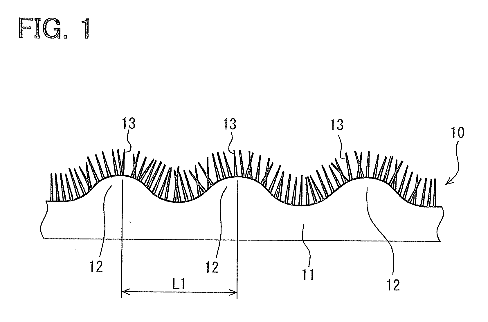
[0023]FIGS. 1, 2A and 2B illustrate an example of a hydrophobic base material 10 according to the embodiment, and the hydrophobic base material 10 is not limited to the illustrated example. Referring to FIG. 1, the hydrophobic base material 10 includes a base 11 with multiple projections 12 at a pitch L1. That is, the hydrophobic base material 10 has a concave-convex surface defined by the multiple projections 12. For example, the pitch L1 is approximately 1 micrometer (μm).

[0024]Further, multiple small projections 13 project from the concave-convex surface. The small projections 13 form an aciculate structure of the hydrophobic base material 10.

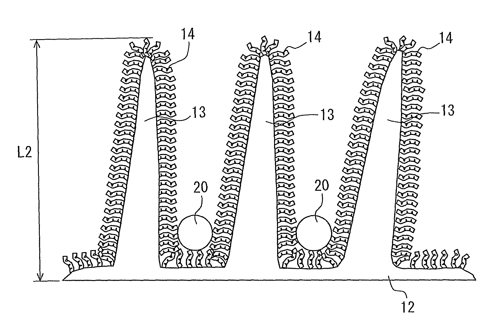
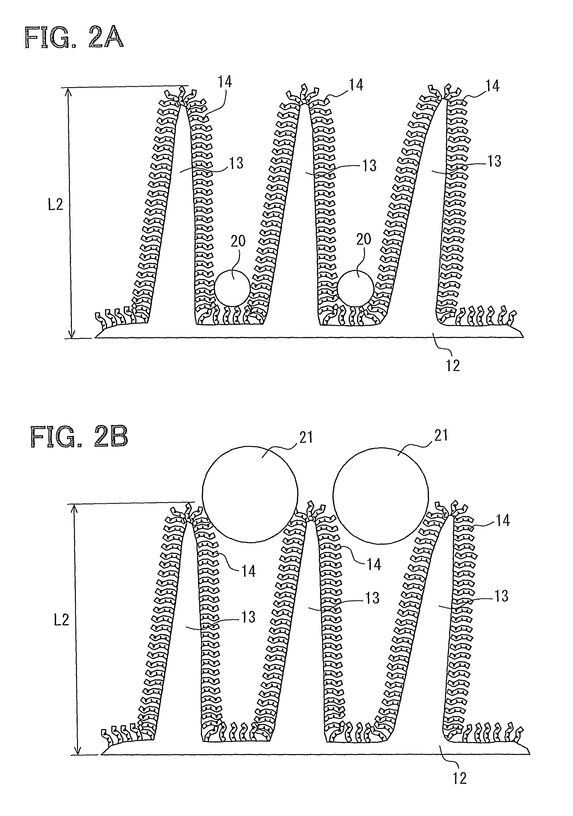
[0025]FIGS. 2A and 2B are enlarged cross-sectional views of the small projections 13 illustrated in FIG. 1. As shown in FIG. 2A, a furry portion having countless fur or hairs is formed on the surface of the small projections 13 and the surface of...


PUM

PropertyMeasurementUnit
projection length L2aaaaaaaaaa
widthaaaaaaaaaa
diameteraaaaaaaaaa

Abstract

A heat transport fluid passage device for a heat transport circuit has a wall defining a passage through which a heat transport fluid flows. The heat transport fluid contains a solvent made of water or an organic substance and fine particles dispersed in the solvent. A hydrophobic membrane is formed on a surface of the wall.

Description

CROSS REFERENCE TO RELATED APPLICATION[0001]This application is based on Japanese Patent Application No. 2010-251091 filed on Nov. 9, 2010, the disclosure of which is incorporated herein by reference.FIELD OF THE INVENTION[0002]The present invention relates to a heat transport fluid passage device defining a passage through which a heat transport fluid containing fine particles flows.BACKGROUND OF THE INVENTION[0003]It has been proposed to add nanoparticles having nanometer-sized diameter in a heat transport fluid that absorbs and transports heat from a heat source so as to improve heat conductivity of the heat transport fluid. Such a heat transport fluid is, for example, described in JP2007-31520A (hereinafter, the document 1) and JP2008-189901A corresponding to US2010 / 0095911A1 (hereinafter, the document 2).[0004]In the heat transport fluid of the document 1, 0.05 or more mass % carbon nanotubes and cellulose derivative or sodium salt thereof are added in a base liquid such as wat...

Claims


Application Information

Patent Timeline
Patent Type & Authority Patents(United States)
IPC IPC(8): F28F13/18C09K5/10F28D15/00F28F1/00F28F21/00F28F23/00
CPCF28D15/00C09K5/10F28F1/00F28F21/00F28F13/185F28F23/00F28F2245/02F28F2245/04
Inventor FUKUTA, RIEHIJIKATA, YOSHIMASAYAMADA, YOSHIYASUYATSUZUKA, SHINICHITAKIGAWA, KENJITOYAMA, TETSUO
Owner DENSO CORP
Learn More