Device for delivery of medical devices to a cardiac valve

a technology for medical devices and cardiac valves, applied in the field of medical devices, can solve the problems of affecting the delivery of medical devices, and affecting the delivery of medical devices, and achieve the effects of reducing the risk of embolism and minimal interference with blood flow

Active Publication Date: 2015-05-05
SWAT MEDICAL AB
View PDF28 Cites 16 Cited by
  • Summary
  • Abstract
  • Description
  • Claims
  • Application Information

AI Technical Summary

Benefits of technology

The present invention is an introducer sheath with an embolic protection unit that can protect the vessels in the aortic arch while delivering medical devices to treat a stenotic valve. It solves the problem of positional issues faced by current catheters and minimizes interference with blood flow. The method involves introducing a catheter with an elongate sheath and an embolic protection unit, and navigating it through the vascular system to the cardiac valve while expanding the protection unit to cover the vessels in the aortic arch. This results in a safer and more effective treatment for stenotic valves.

Problems solved by technology

This is especially important as misalignment has the potential to damage adjacent cardiac structures leading to severe coronary complications.
Placement of the catheter adjacent to a heart valve is hampered by the fact that the heart continues to pump throughout the procedure, giving rise to significant levels of turbulence which the catheter has to overcome to maintain its position.
Furthermore, clotting of the blood leading to emboli is a continuous threat, as potentially they can lead to serious complications such as stroke.
In the US application 2009 / 0030510A1, it is disclosed that a significant obstacle to replacement of an aortic valve is the accurate placement of the medical device to replace the aortic valve.
As the balloons hamper bloodflow by restricting the available cross section for blood flow of the aortic lumen, potentially leading to leading a number of undesired issues.
For instance, deliverable blood volume during the procedure may be reduced having potential dire consequences for the patient.
A problem is that the device is not sufficiently stabilized for secure positioning.
Also in this prior art, a problem is that the device is not sufficiently stabilized for secure positioning.

Method used


Image

  • Device for delivery of medical devices to a cardiac valve
  • Device for delivery of medical devices to a cardiac valve
  • Device for delivery of medical devices to a cardiac valve

Examples


Embodiment Construction

[0043]Specific embodiments of the invention will now be described with reference to the accompanying drawings. This invention may, however, be embodied in many different forms and should not be construed as limited to the embodiments set forth herein; rather, these embodiments are provided so that this disclosure will be thorough and complete, and will fully convey the scope of the invention to those skilled in the art. The terminology used in the detailed description of the embodiments illustrated in the accompanying drawings is not intended to be limiting of the invention. In the drawings, like numbers refer to like elements.

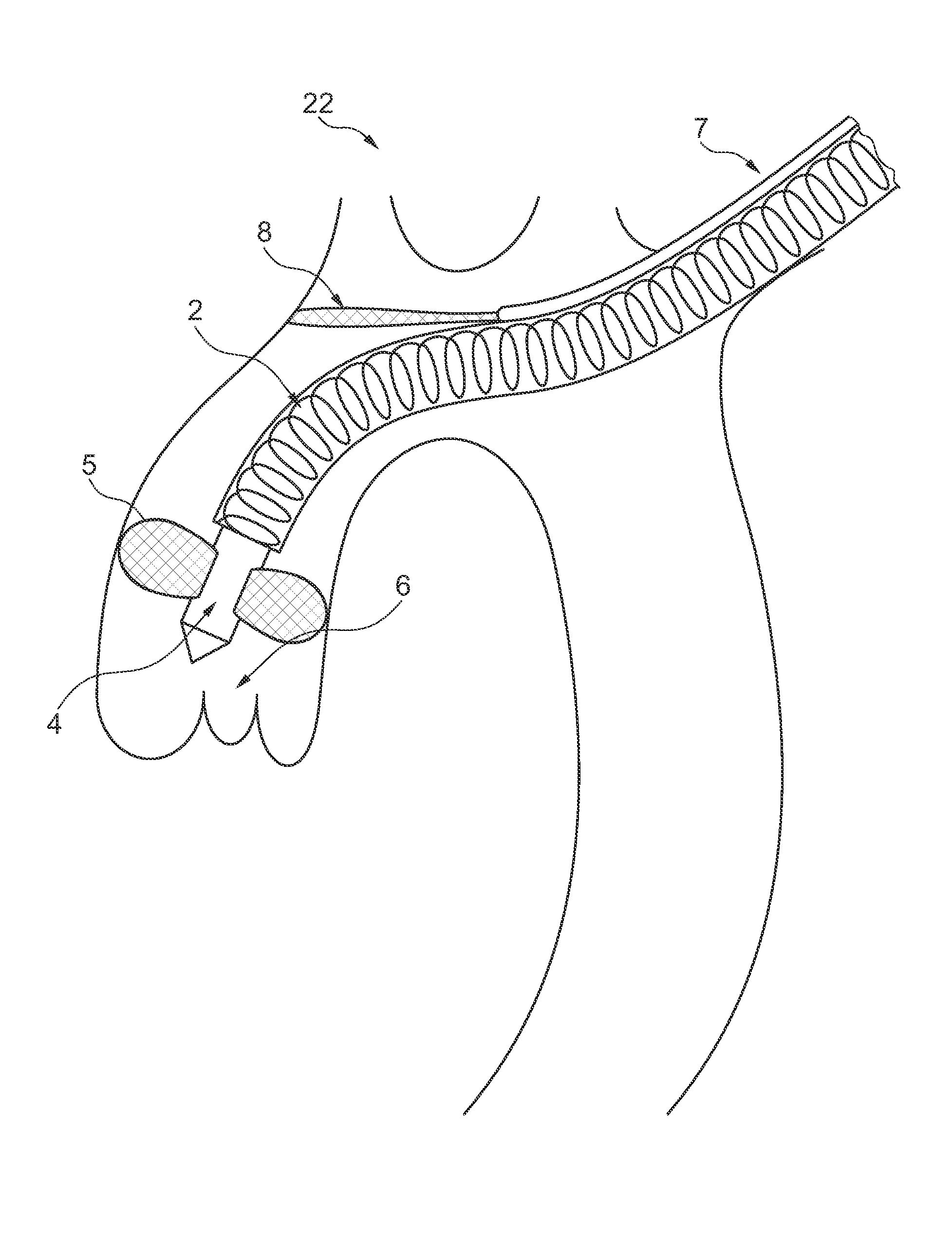
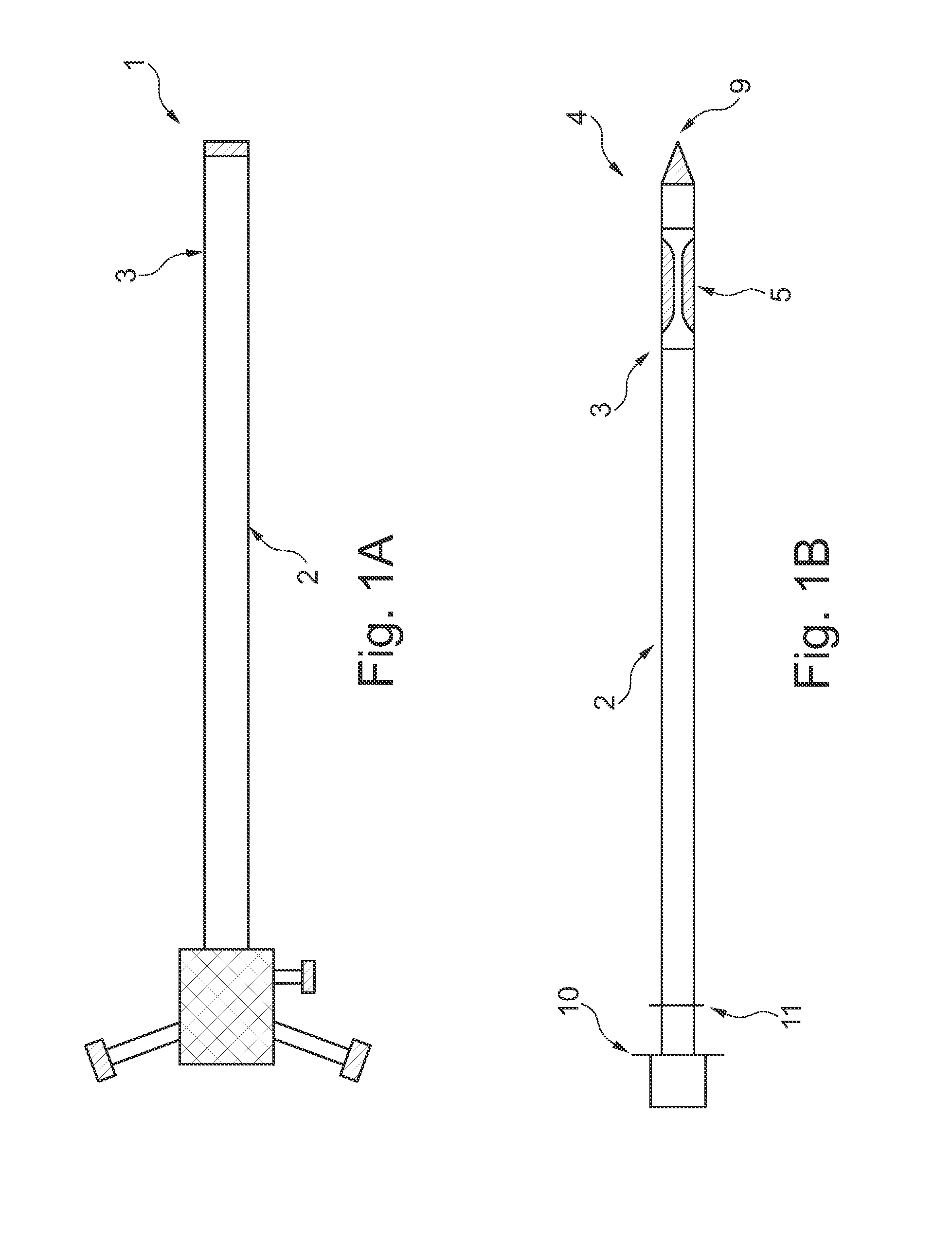
[0044]In an embodiment of the invention according to FIG. 1A, a catheter device 1 for transvascular delivery of a medical device to a cardiac valve region 6 (see e.g. FIG. 4D) of a patient is shown. The catheter device comprises an elongate sheath 2 with a lumen and a distal end 3. In addition in FIG. 1B an elongate member 4 is provided with a distal end porti...


PUM


Abstract

A catheter device for transvascular delivery of a medical device to a cardiac valve region of a patient comprises an elongate sheath with a first lumen, a distal end for positioning at a heart valve, a second lumen that extends parallel to or in the sheath, and an expandable embolic protection filter. The filter is arranged to extend from an orifice of the second lumen and, in the expanded state, covers ostia of the side branch vessels in the aortic arch.

Description

RELATED APPLICATIONS[0001]This application is the U.S. National Phase of and claims priority to International Patent Application No. PCT / EP2012 / 058384, International Filing Date May 7, 2012, entitled Device For Delivery Of Medical Devices To A Cardiac Valve, which claims benefit of European Patent Application No. 11165215.2, filed May 8, 2011 entitled Device And Method For Delivery Of Medical Devices To A Cardiac Valve; and to U.S. Provisional Application Ser. No. 61 / 483,689, filed May 8, 2011 entitled Device And Method For Delivery Of Medical Devices To A Cardiac Valve; all of which are incorporated herein by reference in their entireties.FIELD OF THE INVENTION[0002]This invention pertains in general to the field of medical devices. In particular the invention relates to the positioning of catheters for the delivery of medical devices and the procedures, and more specifically to the transvascular delivery of a medical device to a cardiac valve.BACKGROUND OF THE INVENTION[0003]The h...

Claims


Application Information

Patent Timeline
Patent Type & Authority Patents(United States)
IPC IPC(8): A61F2/24A61F2/01A61F2/958A61M25/04A61M25/10
CPCA61F2/013A61F2/2427A61F2/243A61F2/2433A61F2002/011A61F2250/0059A61M25/04A61M2025/1047A61F2002/016A61F2002/018A61F2230/0071A61M25/0023A61M25/0043A61M25/10A61M25/1011A61M2210/125A61F2/014A61F2/012A61F2/011
Inventor KRAHBICHLER, ERIK
Owner SWAT MEDICAL AB
Why Eureka
Try Eureka