
High-output microspeaker

a high-output, micro-speaker technology, applied in the direction of deaf-aid sets, electrical transducers, transducer details, etc., can solve the problems of lateral vibration, structural limitations in reproducing wideband sound sources, and the micro-speaker did not use wideband sound sources, so as to prevent lateral vibration and improve reliability.

Inactive Publication Date: 2015-05-05
EM TECHNOLOGY CO LTD
View PDF14 Cites 13 Cited by
  • Summary
  • Abstract
  • Description
  • Claims
  • Application Information

AI Technical Summary

Benefits of technology

[0010]Another object of the present invention is to provide a high-output microspeaker which improves reliability by preventing the breakage of an FPCB pattern formed on a damper.
[0027]The high-output microspeaker provided by the present invention can prevent lateral vibrations owing to the position and shape of the support portion of the damper and the patterning shape of an FPCB pattern.
[0028]In addition, the high-output microspeaker provided by the present invention can prevent the breakage of a patterned FPCB circuit by forming a cover layer in stress-concentrated regions, thereby improving reliability.

Problems solved by technology

Conventional microspeakers did not use wideband sound sources due to the limitations of communication technology.
Thus, a conventional microspeaker structure has its limitations in terms of features and reliability.
However, this structure has limitations in reproducing wideband sound sources.
When it comes to a single film type diaphragm, if a film with low rigidity is used or the diaphragm is thinned, in order to improve low frequency performance, this generates dips in sound pressure at mid-to-high frequencies and particular lateral vibrations at low frequencies, thus causing an increase in defect rate.
On the other hand, if the diaphragm is thickened or a film with high rigidity is used, this degrades low frequency performance and results in poor sound balance.
However, this structure also produces severe lateral vibrations at high-output mode, and can even cause coil breakage, which may lead to serious problems in terms of reliability.
The components and shape of this damper greatly affect the features and reliability of a microspeaker when configuring the damper.
A wrongly-configured damper could be more subject to wire breakage than a voice coil lead-out structure and cause difficulties in correcting lateral vibrations at a particular mode.

Method used


Image

  • High-output microspeaker
  • High-output microspeaker
  • High-output microspeaker

Examples


first embodiment

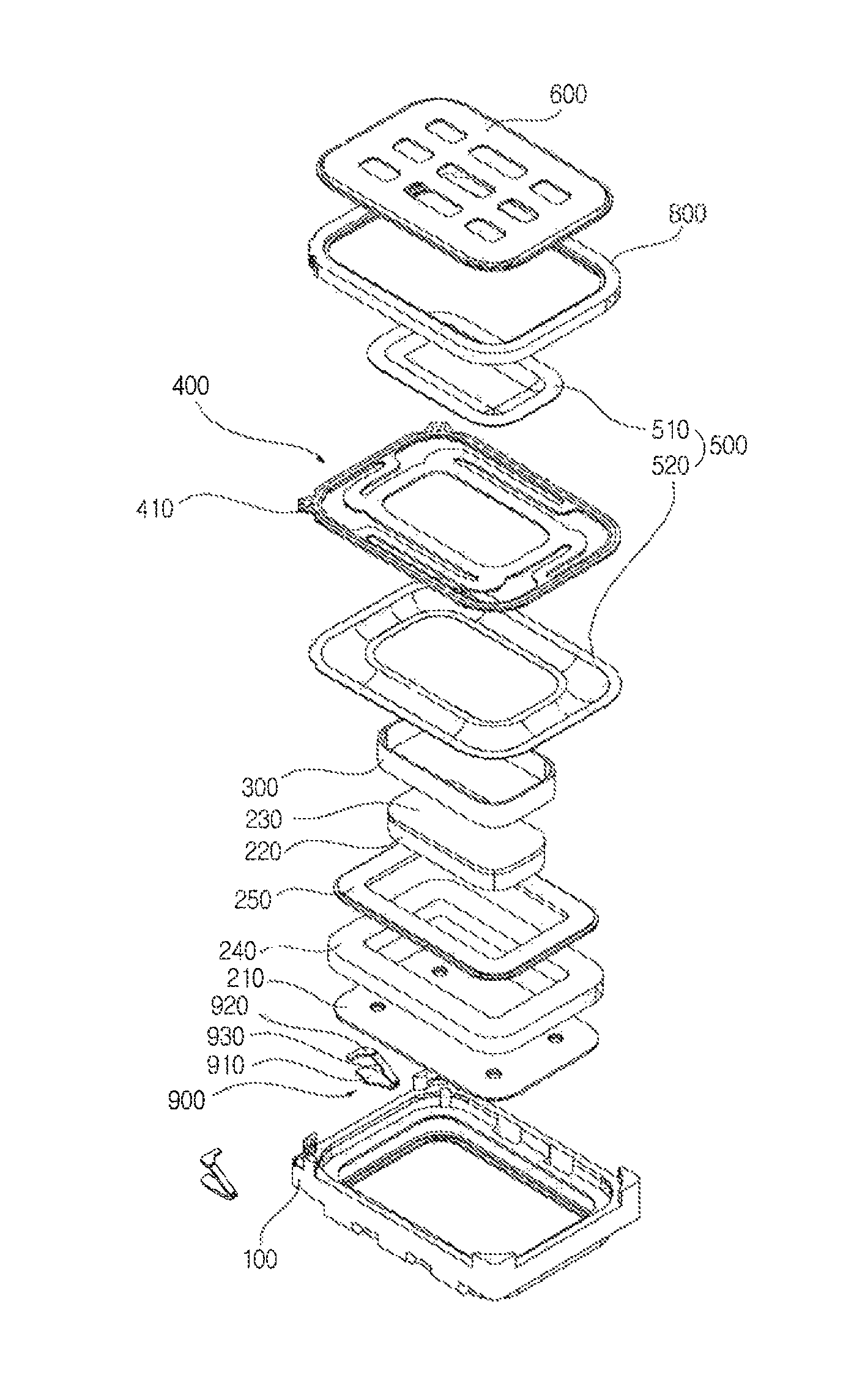
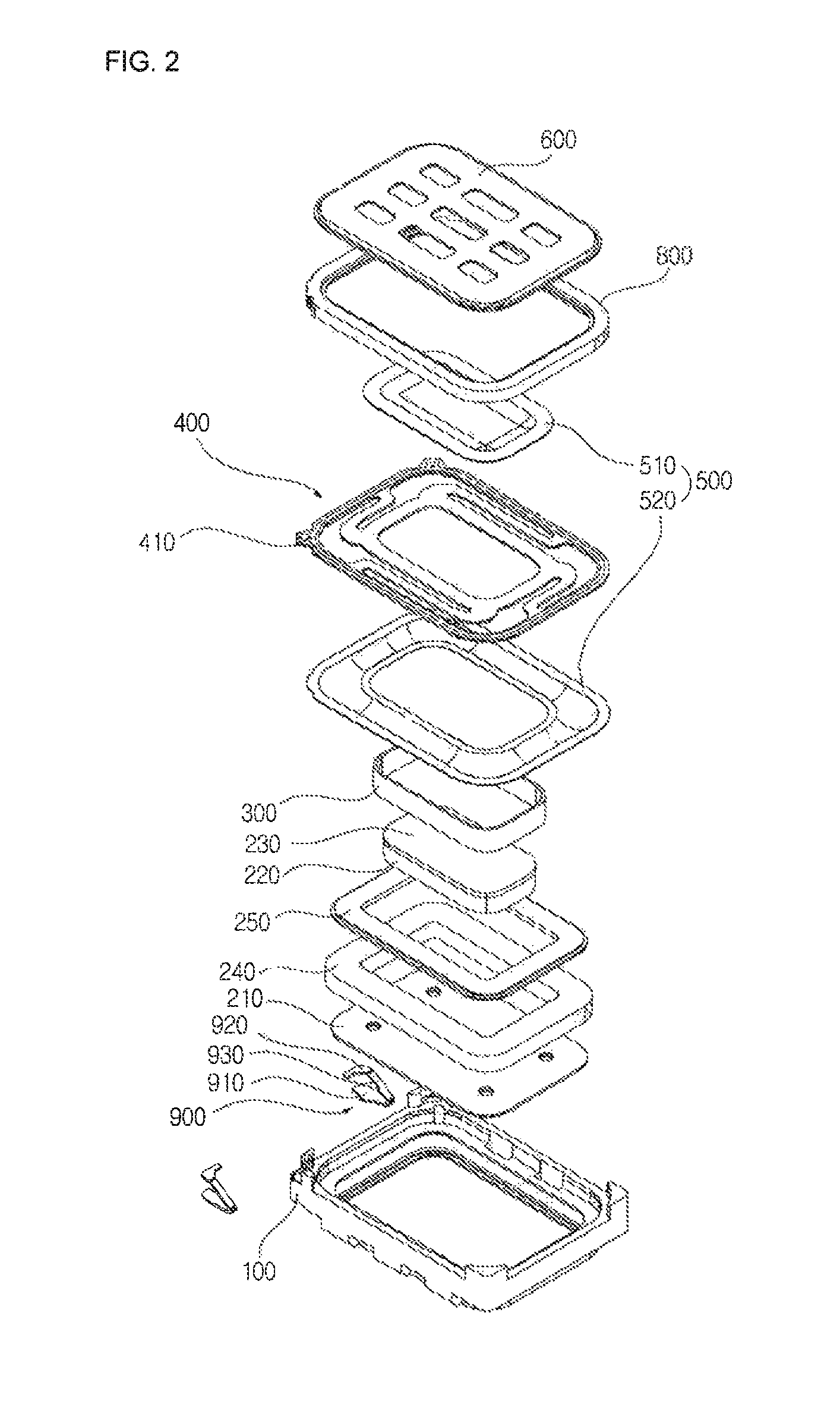
[0053]The damper 400a includes an inner portion 410a to which a center diaphragm, a side diaphragm and a voice coil are attached, an outer portion 420a being in contact with a frame and a protector, and support portions 430a connecting and supporting the inner portion 410a and the outer portion 420a. Also, connecting portions 422a for connecting to terminals such as pad type terminals 900 are provided on one side of the outer portion 420a. The damper 400a is overall in the shape of a rectangle, and its corners are rounded. The outer portion 420a has a rectangular shape with corners rounded along the shape of the damper 400a and includes four sides, and the inner portion 410 likewise has a rectangular shape with rounded corners and includes four sides. Since the side diaphragm 520 and the voice coil 300 should be attached to the bottom of the inner portion 410a, the width of the inner portion 410a should be greater than the sum of the width of the seating portion of the side diaphra...

third embodiment

[0058]In a damper 400c an FPCB lower surface pattern 450c is formed only at an outer portion 420c and support portions 430c, but not at an inner portion 410a. While land portions 438c are formed only at two of the support portions 430c, the FPCB lower surface pattern 450c is formed at all the support portions 430c in order to form a symmetrical structure. That is, a dummy pattern is formed at two of the support portions 430c. The FPCB lower surface pattern 450c is configured such that the pattern width is somewhat larger at the boundaries between the regions formed on inner curved portions 434a of the support portions 430c and the inner portion 410a.

[0059]FIG. 10 is a view showing a damper for a high-output microspeaker according to a fourth embodiment of the present invention. The fourth embodiment is identical to the second and third embodiments, except for the shape of an FPCB lower surface pattern, so descriptions of components other than the FPCB lower surface pattern will be...


PUM


Abstract

The present invention relates to a high-output microspeaker, and more particularly, to a high-output microspeaker which includes a damper for preventing lateral vibrations of a diaphragm. The present invention discloses a high-output microspeaker, comprising: a frame; a protector; a yoke assembly coupled to the frame and including a magnet; a diaphragm provided in the frame and producing vibration; a voice coil coupled to the diaphragm and vibrating the diaphragm; a terminal provided on one side of the frame and providing an electrical connection between the lead wire of the voice coil and an external terminal; and a damper formed of an FPCB that includes an inner portion to which a center diaphragm, a side diaphragm and the voice coil are attached, an outer portion to which the side diaphragm is attached and which is in contact with the frame and the protector, a support portion functioning to connect the voice coil, the outer portion and the inner portion and including a land portion to which the lead-in wire of the coil is soldered or welded, and a connecting portion extending outward from the outer portion and providing an electrical connection between the terminal provided on the frame and the outer portion.

Description

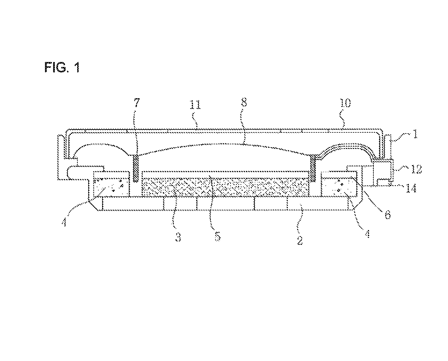
TECHNICAL FIELD[0001]The present invention relates to a high-output microspeaker, and more particularly, to a high-output microspeaker which includes a damper for preventing lateral vibrations of a diaphragm.BACKGROUND ART[0002]Conventional microspeakers did not use wideband sound sources due to the limitations of communication technology. However, with the advancement of information and communication technology, the bandwidth of a sound source to be reproduced by a speaker has become wider and the required output has increased. Thus, a conventional microspeaker structure has its limitations in terms of features and reliability.[0003]FIG. 1 is a sectional view showing a conventional sound transducer.[0004]As shown, a typical sound transducer (speaker) includes a frame 1, a yoke 2 inserted and mounted inside the frame 1, an inner ring magnet 3 and an outer ring magnet 4 for transmitting a magnetic flux to the yoke 2 or receiving the magnetic flux from the yoke 2, an inner ring top pl...

Claims


Application Information

Patent Timeline
Patent Type & Authority Patents(United States)
IPC IPC(8): H04R25/00H04R9/04
CPCH04R9/043H04R9/045H04R7/20H04R9/02
Inventor KWON, JOONG HAKKIM, CHEON MYEONGKIM, JI HOONCHOI, KYU DONG
Owner EM TECHNOLOGY CO LTD
Learn More