Methods and apparatus for recovering phase and amplitude from intensity images

a phase and intensity image technology, applied in the field of intensity image recovery methods and apparatuses, can solve the problems of inability to efficiently recover inability to reduce computational complexity, and inability to achieve the effect of reducing computational complexity, improving robustness to noise, and efficiently recovering phase and phase of optical fields

Inactive Publication Date: 2015-05-05
NANYANG TECH UNIV
View PDF4 Cites 7 Cited by
  • Summary
  • Abstract
  • Description
  • Claims
  • Application Information

AI Technical Summary

Benefits of technology

[0011]The invention relates to an experimental situation in which an intensity image is collected at each of a plurality of locations spaced apart in a propagation direction of a light beam. Thus, typical embodiments of the invention do not require a reference beam, or rely on interference phenomena. Wavefront propagation means that that plurality of images encode phase information, and the intensity images are used in combination to extract the phase information. The invention proposes in general terms that information from the intensity images is combined using a Kalman filter which assumes that at least one co-variance matrix has a diagonal form. This leads to considerable reduction in computational complexity.
[0020]The experimental setup for wave propagation based methods is simpler, compared to the interference methods (phase contrast microscopy, differential interference contrast microscopy, and digital holography microscopy). Fewer optical components are required. It also avoids the phase unwrapping problem associated with those methods. The needed components are inexpensive optics and semiconductor components, such as a laser diode and an image sensor. The low component cost in combination with the auto focusing capabilities of the preferred embodiments, make it possible to manufacture such system for a very low cost.

Problems solved by technology

This leads to considerable reduction in computational complexity.
However, whereas the ACEKF method of [1] is computationally unwieldy and impractical, preferred embodiments of the present invention are very efficient.
It seems to be feasible for phase recovery in real-time, which is entirely unfeasible with ACEKF.

Method used


Image

  • Methods and apparatus for recovering phase and amplitude from intensity images
  • Methods and apparatus for recovering phase and amplitude from intensity images
  • Methods and apparatus for recovering phase and amplitude from intensity images

Examples


Embodiment Construction

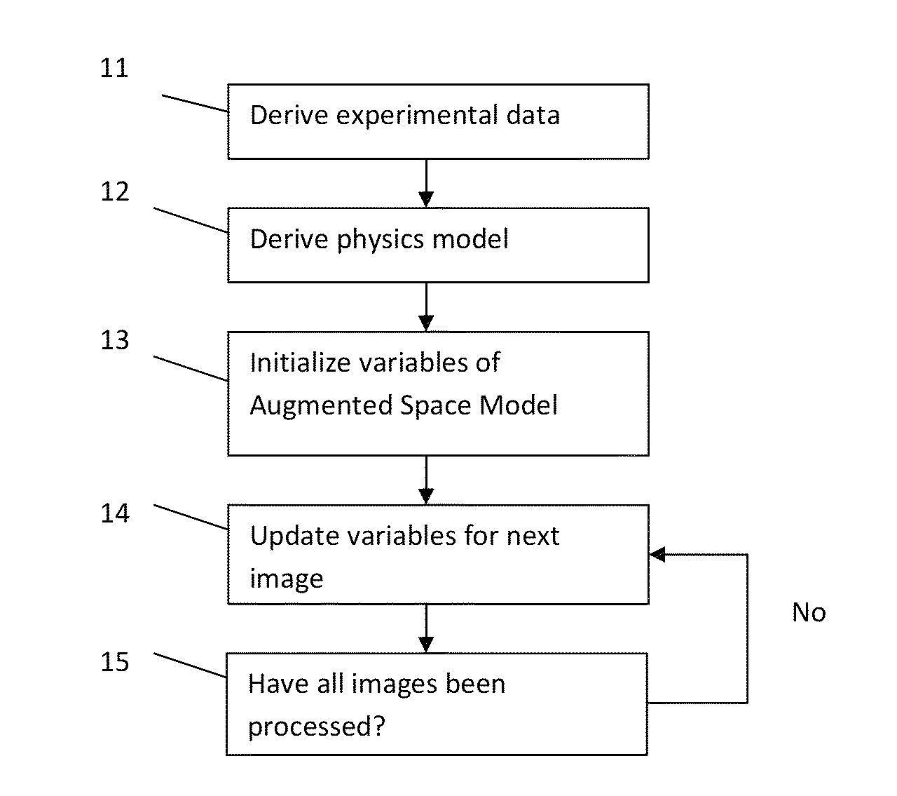
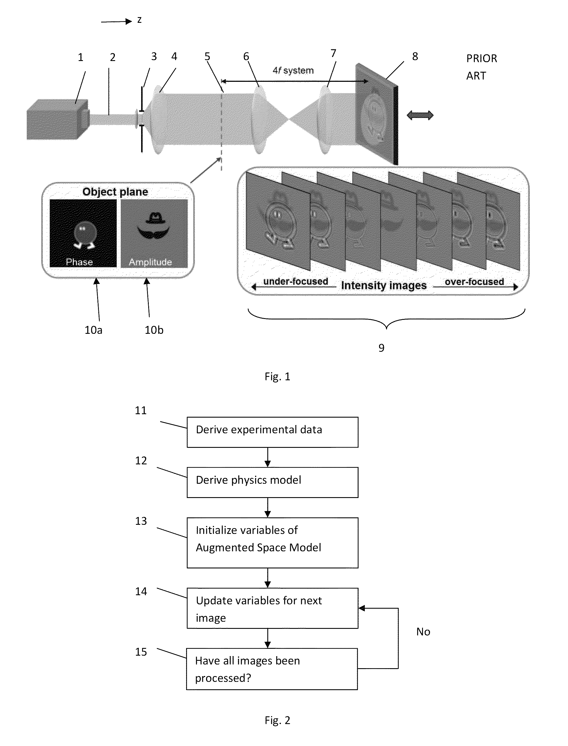
[0031]A flow chart of the embodiment is shown in FIG. 2. Step 11 is to set up experimental conditions, such as those in FIG. 1, to collect a series of intensity images in different parallel planes. The images are M1×M2 pixels. Step 12 is to use the parameters of the experimental set-up to generate a physical model describing it. These steps are the same as used, for example, in [1], as described above.

[0032]The remaining steps employ a novel augmented state space model. In step 13 parameters of the model are initialised. In step 14, the data for a first of the series of images is used to update the model. As described below this makes use of a novel phase reconstruction algorithm, assuming a diagonal covariance matrix. Step 14 is performed repeatedly for successive ones of the series of images, until all images have been processed.

1. Problem Description and Physical Model

[0033]We aim at estimating the 2D complex-field A(x,y,z0) at the focal plane z0, from a sequence of noisy intensi...


PUM


Abstract

An intensity image is collected at each of a plurality of locations spaced apart in a propagation direction of a light beam. Information from the intensity images is combined using a Kalman filter which assumes that at least one co-variance matrix has a diagonal form. This leads to considerable reduction in computational complexity. An augmented Kalman filter model (augmented space state model) is used in place of the standard Kalman filter model. The augmented Kalman filter improves the robustness to noise.

Description

FIELD OF THE INVENTION[0001]The present invention relates to methods and apparatus to obtain phase information characterizing light, using a plurality of images encoding information about the intensity of the light.BACKGROUND OF THE INVENTION[0002]When coherent (laser) light passes through or reflects from an object, its amplitude and phase are altered as it continues to propagate. Phase perturbations contain important information about an object. For example, transparent biological cells are invisible in a focused microscope, but impart distinct phase changes. Data about these phase changes can find useful applications in morphology analysis of cell, or cell-cycle analysis without labelling. Such applications are relevant for biology and biomedical engineering, e.g., for detecting cancer cells. Moreover, there are various applications in materials science.[0003]It is noteworthy that only the intensity of light can be measured directly, since phase oscillates far too quickly, and th...

Claims


Application Information

Patent Timeline
Patent Type & Authority Patents(United States)
IPC IPC(8): G06K9/00G02B27/50G03B13/32G06T7/00
CPCG06T7/0002G06T2207/10016G06T2207/20056G06T2207/20076G06T2207/30024G03H1/0866G03H2001/0447
Inventor DAUWELS, JUSTINZHONG, JINGSHAN
Owner NANYANG TECH UNIV
Why Eureka
Try Eureka