Adhesive bone conduction hearing device
a bone conduction and hearing device technology, applied in the direction of hearing aid mounting/interconnection, stereophonic arrangments, stereophonic arrangments, etc., can solve the problems of unsuitable pressure points, unsuitable pressure points, and unsatisfactory and reliably provided devices, etc., to avoid unsuitable pressure points. , the effect of avoiding unsuitable pressure points
- Summary
- Abstract
- Description
- Claims
- Application Information
AI Technical Summary
Benefits of technology
Problems solved by technology
Method used
Image
Examples
example 1
Headbands
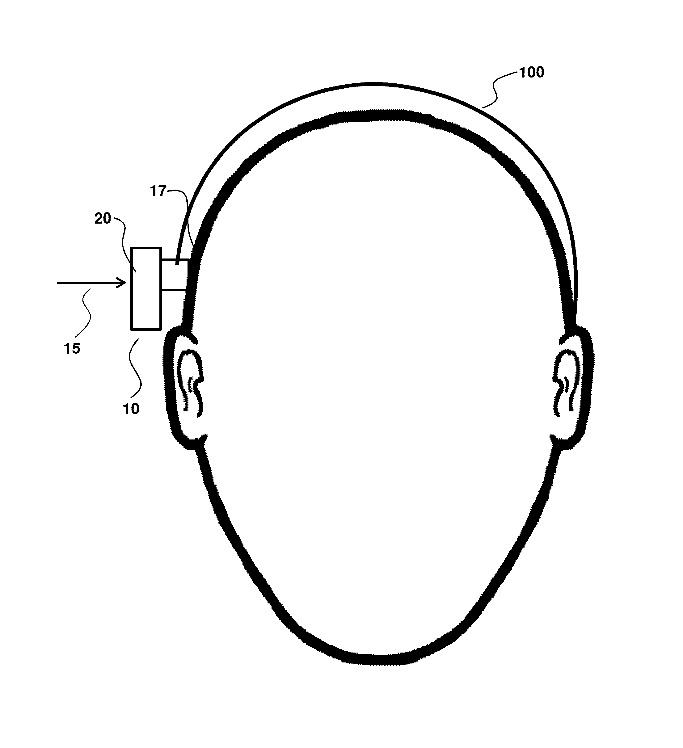
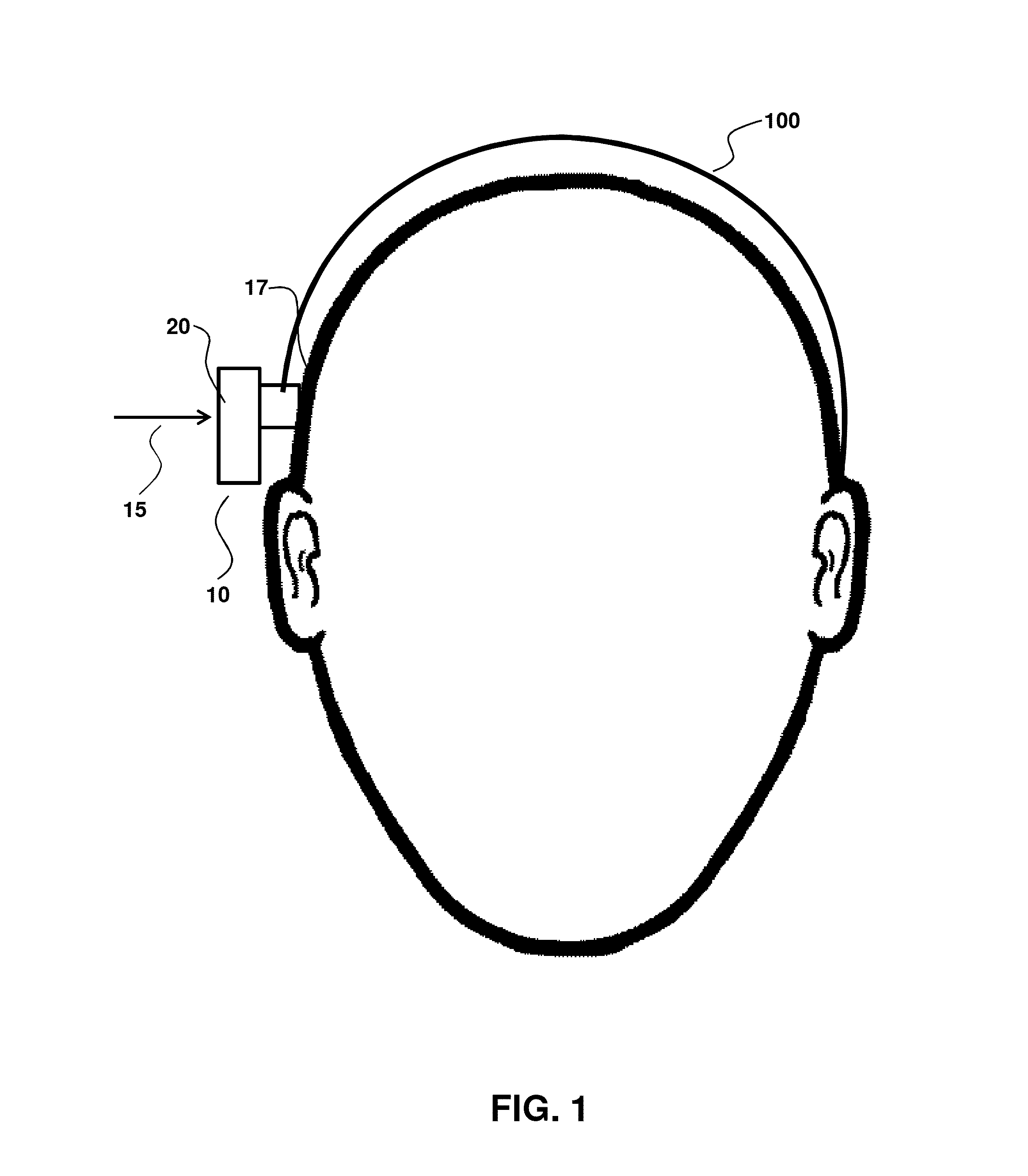
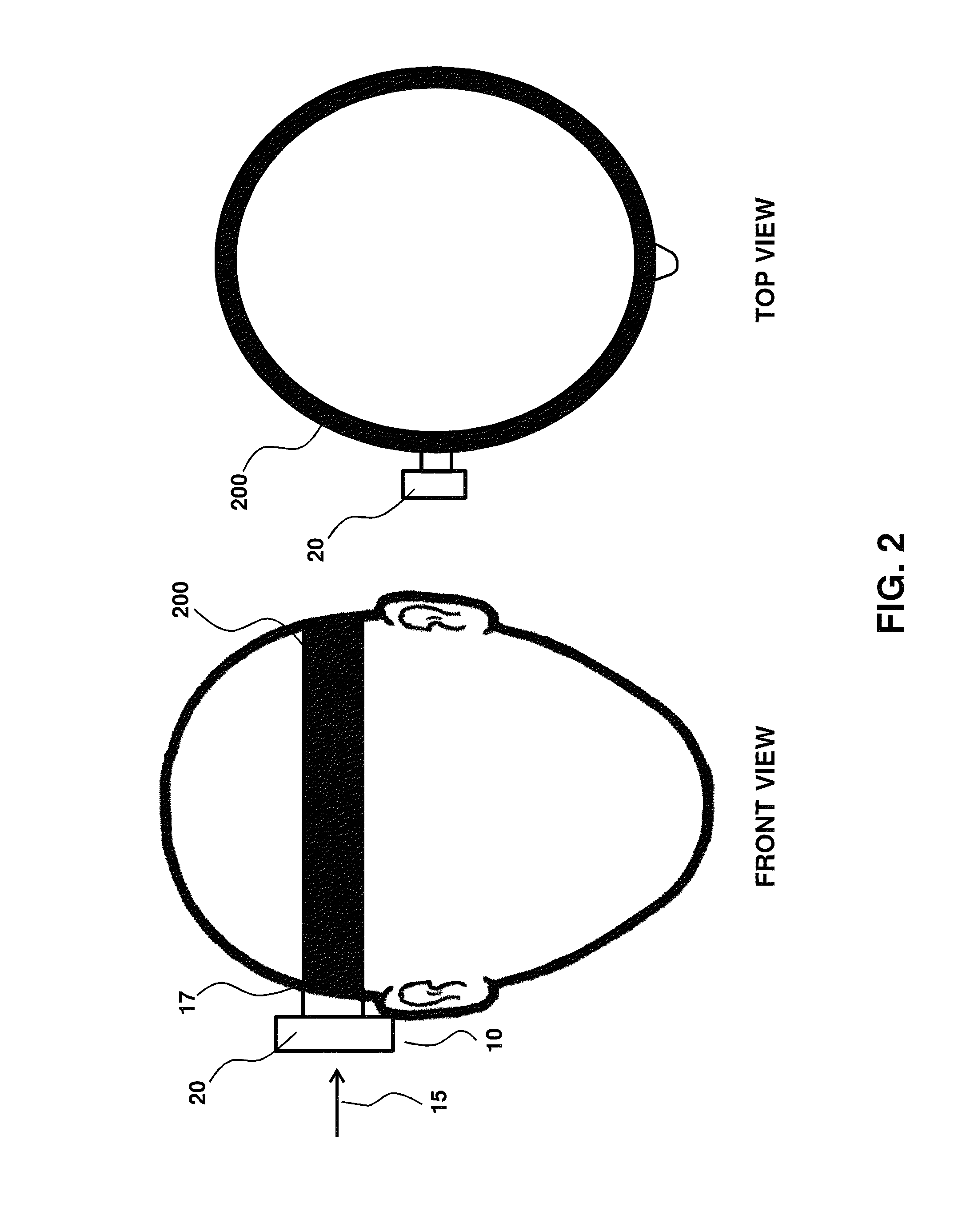
[0066]FIGS. 1-2 illustrate an embodiment where a headband 100 (FIG. 1) or a softband 200 (FIG. 2) provide a normal force 15 that secures an external component 20 of a hearing device 10 to a user surface 17. This example suffers a number of disadvantages, such as the band 100 or 200 being uncomfortable, unsightly and unreliable during use, particularly as to providing a well-defined and controlled normal force. Accordingly, an aspect of the invention relates to an adhesive anchor that is not a headband, softband or any other band that transits around the head.
example 2
Magnets
[0067]FIG. 3 illustrates an embodiment where magnets provide a normal force to secure an external component 20 to a user surface 17. In this embodiment, the magnets include internal magnets 300 and external magnets 310 secured within magnet spacer 311, relative to user surface 17 that corresponds to skin 18 overlying the skull 19. In this aspect, the magnets 300 and 310 may be considered to form an adhesive anchor that is partially removable in that upon removal of the external component the internal magnets 300 remain implanted in the user. In an aspect, the magnet spacer 311 has an inner surface 312 shaped for conformal contact with the skin 18 overlying the skull 19.
example 3
Adhesives
[0068]FIG. 4 describes the simplest form of an adhesive anchor 400 that secures the external component 20 to the user surface 17. In an embodiment, the adhesive anchor is an adhesive material having a first and a second surface that is sticky, so that the first end sticks to the user surface 17 and the second surface to the external component 20. A drawback with this embodiment is that the generated normal force 15 is often too low to provide good vibration transmission. This is indicated by the short length of the normal force arrow 15.
[0069]FIGS. 7-10 illustrate an embodiment where a self-adhesive anchor, such as an adhesive layer, generates a sufficient normal force to transmit vibration to the skull while maintaining reliability and comfort, including over use on the time frame of a day or more. FIG. 7 illustrates an adhesive anchor 700 that may be used, for example, in an adult. FIG. 7A is a perspective view of a fully assembled self-adhesive anchor 700 with a top adhe...
PUM
 Abstract
Description
Claims
Application Information
 - R&D
- Intellectual Property
- Life Sciences
- Materials
- Tech Scout
- Unparalleled Data Quality
- Higher Quality Content
- 60% Fewer Hallucinations
Browse by: Latest US Patents, China's latest patents, Technical Efficacy Thesaurus, Application Domain, Technology Topic, Popular Technical Reports.
© 2025 PatSnap. All rights reserved.Legal|Privacy policy|Modern Slavery Act Transparency Statement|Sitemap|About US| Contact US: help@patsnap.com


