
System and method for controlling oil pump

a technology of oil pump and control system, which is applied in the direction of engine revolution, analogue process for specific applications, instruments, etc., can solve the problems of fuel efficiency decline, difficult adjustment of oil pressure, and low efficiency of diesel engines with low engine revolution speed, so as to improve fuel efficiency and reduce oil pressure

Active Publication Date: 2015-05-12
HYUNDAI MOTOR CO LTD +1
View PDF59 Cites 1 Cited by
  • Summary
  • Abstract
  • Description
  • Claims
  • Application Information

AI Technical Summary

Benefits of technology

The oil pump control system and method described in this patent can adjust oil pressure based on changes in engine load, which helps to protect engine lubricants and improve fuel efficiency by reducing oil pressure in low load areas.

Problems solved by technology

Since the mechanical variable oil pump varies the volume of the pumping space while moving the outer ring so as to maintain uniform oil pressure regardless of the number of revolutions of the engine, there is a problem in that efficiency of a diesel engine having a low revolution speed of the engine is deteriorated.
Further, in the mechanical variable oil pump in the related art, a variable time and the oil pressure establish a sort of trade-off relation, so that when the variable start point is low pressure, it is difficult to adjust oil pressure in a full load, and when the oil pressure in the full load is adjusted, pressure of the variable start point increases, thereby causing fuel efficiency to decrease.
In order to solve the problem, an electronic oil pump for electrically controlling an oil pump by several variables has been developed, but the electronic oil pump is also controlled without considering a load of an engine, so that there is a problem in that an engine lubrication system cannot be sufficiently protected from oil pressure under a high load condition.
Accordingly, the related art has a problem in that it is difficult to satisfy both an aspect of improving fuel efficiency and an aspect of protecting an engine lubrication system.

Method used


Image

  • System and method for controlling oil pump
  • System and method for controlling oil pump
  • System and method for controlling oil pump

Examples


Embodiment Construction

[0041]Reference will now be made in detail to various embodiments of the present invention(s), examples of which are illustrated in the accompanying drawings and described below. While the invention(s) will be described in conjunction with exemplary embodiments, it will be understood that the present description is not intended to limit the invention(s) to those exemplary embodiments. On the contrary, the invention(s) is / are intended to cover not only the exemplary embodiments, but also various alternatives, modifications, equivalents and other embodiments, which may be included within the spirit and scope of the invention as defined by the appended claims.

[0042]Hereinafter, exemplary embodiments of the present invention will be described in detail with reference to the accompanying drawings.

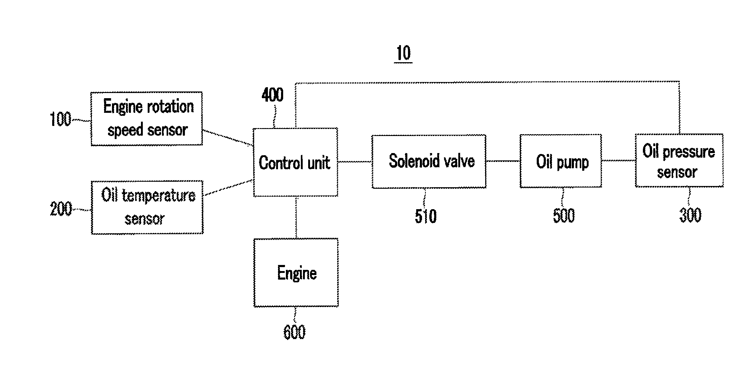
[0043]FIG. 1 is a configuration diagram of a control system 10 of an oil pump 500 according to an exemplary embodiment of the present invention.

[0044]As illustrated in FIG. 1, the control system...


PUM


Abstract

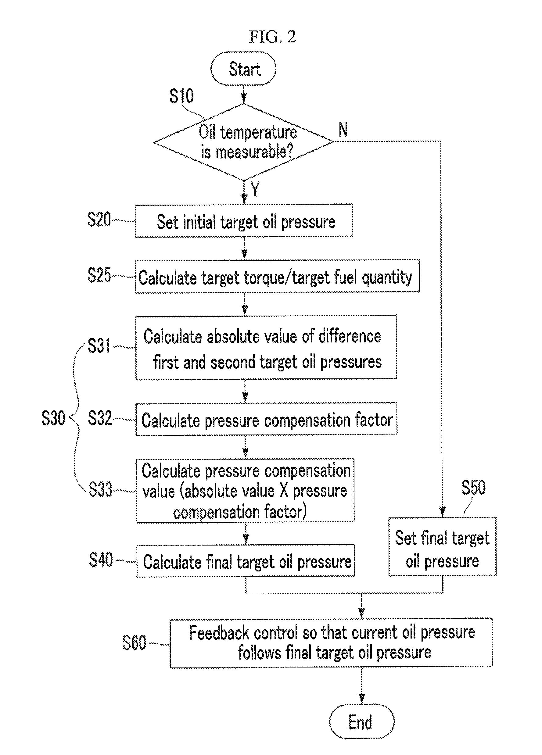
Disclosed are an oil pump control system and method, the oil pump control method including setting an initial target oil pressure of the oil pump based on a rotation speed of an engine or an oil temperature, determining a pressure compensation value by considering the target torque or target fuel quantity of the engine based on the initial target oil pressure, determining a final target oil pressure by adding the pressure compensation value to the initial target oil pressure, and feedback-controlling the oil pump so that current oil pressure measured in real time follows the final target oil pressure.

Description

CROSS-REFERENCE TO RELATED APPLICATION[0001]The present application claims priority to Korean Patent Application No. 10-2012-0110027 filed on Oct. 4, 2012, the entire contents of which is incorporated herein for all purposes by this reference.BACKGROUND OF THE INVENTION[0002]1. Field of the Invention[0003]The present invention relates to an oil pump control system of a vehicle and an oil pump control method for a vehicle.[0004]2. Description of Related Art[0005]A mechanical variable oil pump applied to a vehicle engine lubrication system in the related art generally includes a driving gear for receiving power from an engine, a rotor rotated by rotation force of the driving gear and including a plurality of vanes, a pivot pin fixed to a housing, an outer ring for varying a volume of a pumping space formed between the vanes by pivoting based on the pivot pin, and a spring for elastically supporting the outer ring.[0006]Since the mechanical variable oil pump varies the volume of the pu...

Claims


Application Information

Patent Timeline
Patent Type & Authority Patents(United States)
IPC IPC(8): G06F7/00B60W10/06B60W10/30F01M1/16
CPCF01M1/16B60W10/06B60W10/30F01M2250/64F01M1/02
Inventor LEE, SUNGHA
Owner HYUNDAI MOTOR CO LTD
Learn More