Supercharge Your Innovation With Domain-Expert AI Agents!

Hydraulic excavator

a technology of hydraulic excavators and excavators, which is applied in the direction of mechanical machines/dredgers, machines/engines, tractors, etc., can solve the problems of increasing the difficulty of replacement work, and achieve the effect of facilitating replacement work

Active Publication Date: 2015-05-19
KOMATSU LTD
View PDF8 Cites 2 Cited by
  • Summary
  • Abstract
  • Description
  • Claims
  • Application Information

AI Technical Summary

Benefits of technology

The present invention provides a hydraulic excavator with optimized attachment locations for filters, making filter replacement work more efficient. The filter devices are located close to each other and can be easily accessed through the opening of the openable door during filter replacement. There is sufficient work space around the filter devices during filter replacement. The layout of the filter devices is optimized based on their replacement lives, making maintenance work more efficient. This results in more efficient filter replacement work and maintenance work than with a conventional configuration.

Problems solved by technology

However, the following problems were encountered with the conventional hydraulic excavator discussed above.
Therefore, if space was necessary under the filters during their replacement, the work entailed by the replacement might become more difficult because a plurality of filters were provided at the same height location.

Method used


Image

  • Hydraulic excavator
  • Hydraulic excavator
  • Hydraulic excavator

Examples


Embodiment Construction

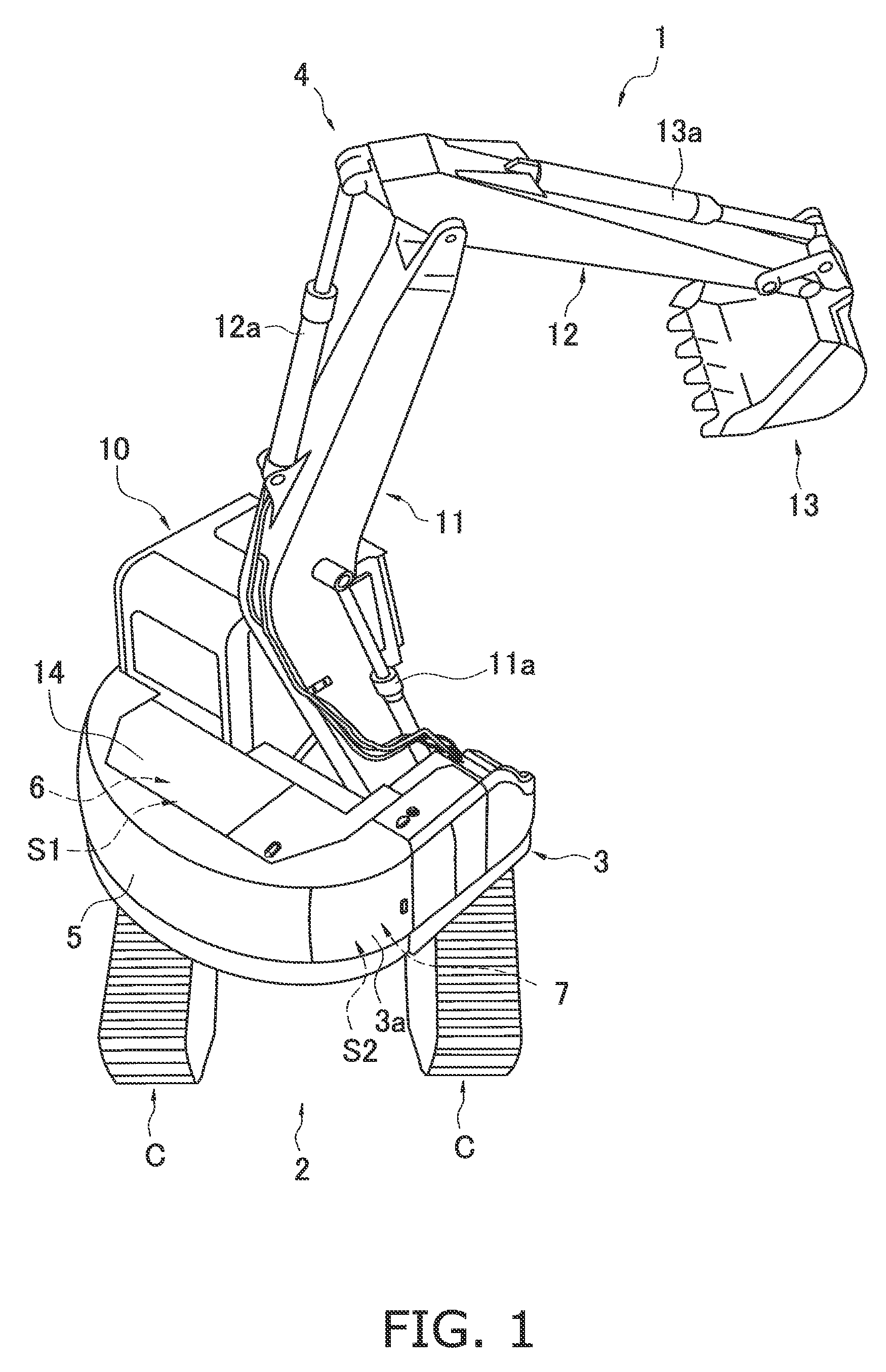
[0029]The hydraulic excavator 1 pertaining to an embodiment of the present invention will be described through reference to FIGS. 1 to 6. The “forward and backward” and “left and right” directions used in the following description refer to the directions as seen by the operator seated in the seat inside the cab 10 of the hydraulic excavator 1.

[0030]The hydraulic excavator 1 pertaining to this embodiment is a short rear-end swing type of hydraulic excavator, and as shown in FIG. 1, comprises a lower traveling unit 2, an upper structure 3, a work implement 4, a counterweight 5, an engine 6, and the cab 10.

[0031]The lower traveling unit 2 moves the hydraulic excavator 1 forward and backward by rotating crawler belts C wrapped around the left and right end portions in the travel direction, and has the upper structure 3 installed in a revolvable state on top.

[0032]The upper structure 3 is able to revolve in any direction on top of the lower traveling unit 2, and is equipped on its upper ...


PUM


Abstract

A hydraulic excavator is provided with a lower traveling unit, an upper structure, an engine, a hydraulic pump, an engine compartment, a pump compartment and a plurality of filter devices. The upper structure is rotatably disposed on the lower traveling unit. The pump compartment provided on the upper structure for housing the hydraulic pump. The pump compartment has a door that allows access to an interior of the pump compartment. The filter devices, which are disposed adjacent to each other, are disposed at positions that are mutually offset in a height direction of the hydraulic excavator.

Description

BACKGROUND[0001]1. Field of the Invention[0002]The present invention relates to a hydraulic excavator in which are installed various kinds of filter device that filter out impurities contained in engine oil, fuel, etc.[0003]2. Background Information[0004]Filter devices for filtering out impurities contained in engine oil or diesel fuel are installed in modern hydraulic excavators and other such construction machines. For example, Japanese Laid-Open Patent Application 2001-288777 discloses a hydraulic excavator in which a fuel filter, a working fluid filter, and other such auxiliary devices are provided on the inside of an openable door provided to the house of a construction machine so that auxiliary devices that require inspection and maintenance on a regular basis will be disposed at easily accessible locations, thereby improving efficiency and ease of inspection and maintenance.SUMMARY[0005]However, the following problems were encountered with the conventional hydraulic excavator...

Claims


Application Information

Patent Timeline
Patent Type & Authority Patents(United States)
IPC IPC(8): E02F9/08F01N3/00
CPCE02F9/0858E02F9/0833E02F9/0866F01N3/00
Inventor KOGA, MITSUHIROTSUJIMOTO, NAOKI
Owner KOMATSU LTD
Features
  • R&D
  • Intellectual Property
  • Life Sciences
  • Materials
  • Tech Scout
  • Unparalleled Data Quality
  • Higher Quality Content
  • 60% Fewer Hallucinations
Learn More