
Rotary actuator for energy efficient ice cube dispenser door system

a technology of ice cube dispenser and actuator, which is applied in the direction of operating means/releasing devices of valves, liquid transfer devices, light and heating apparatus, etc., can solve the problems achieve the effect of slowing the closing speed of the dispenser door, reducing the sound of the door, and moderate speed

Active Publication Date: 2015-05-19
ILLINOIS TOOL WORKS INC
View PDF20 Cites 2 Cited by
  • Summary
  • Abstract
  • Description
  • Claims
  • Application Information

AI Technical Summary

Benefits of technology

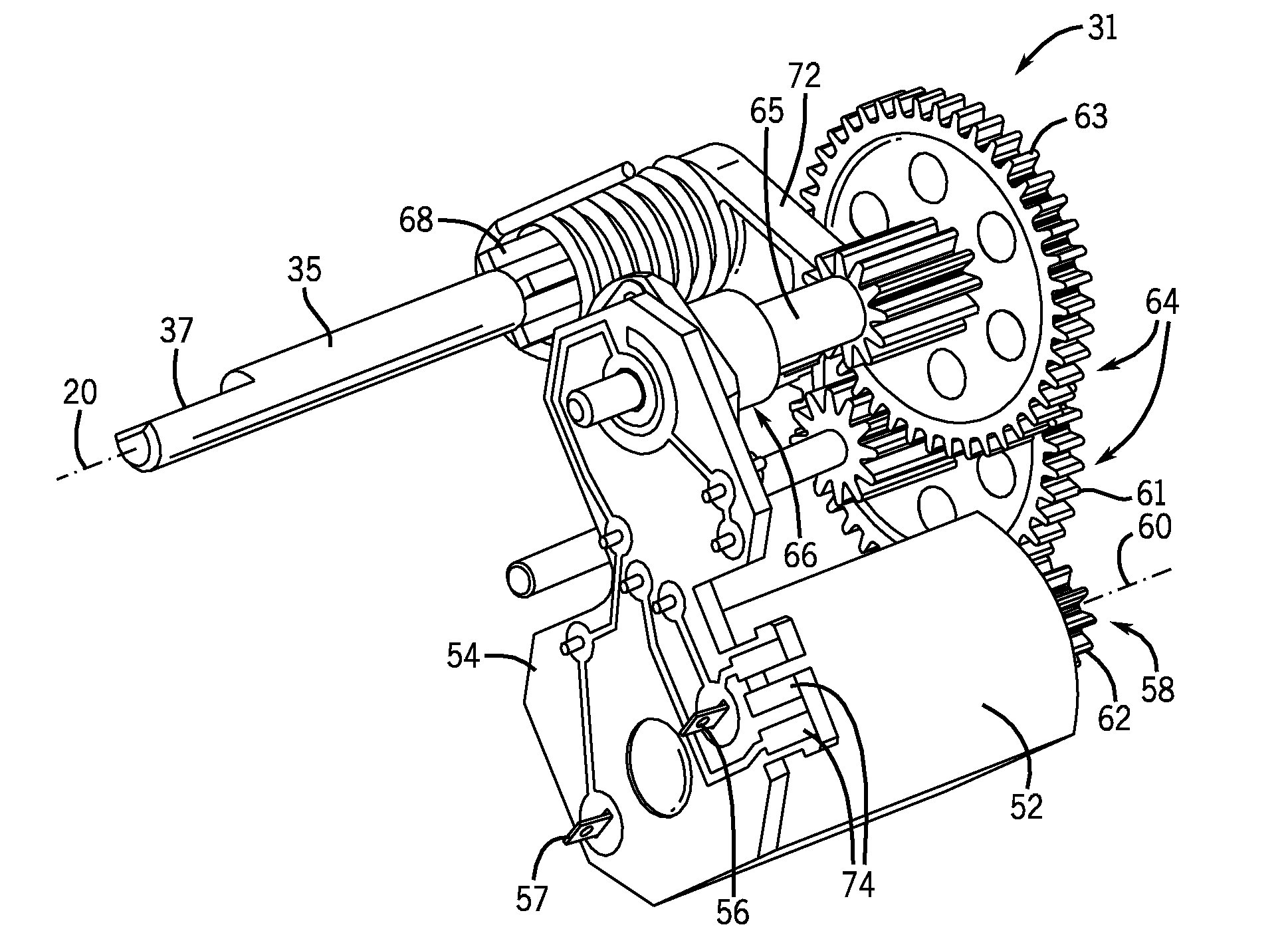
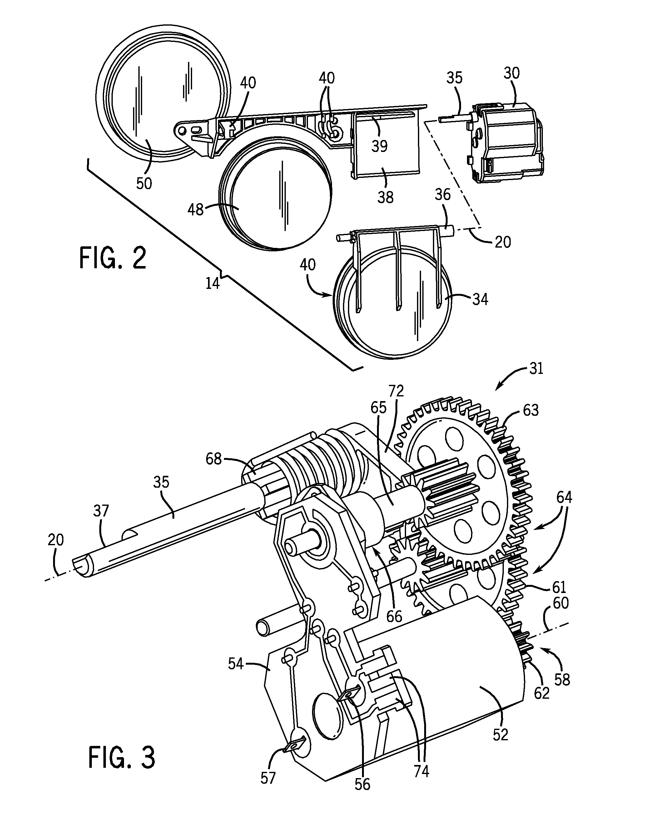
[0006]The present invention provides an actuator for an ice dispenser door that employs a low-power DC motor. A gear train connecting to the DC motor and the self regulating properties of DC motors moderate the speed of opening of the dispenser door when power is applied to the motor. Further, generative electrical braking through the motor slows the closing speed of the dispenser door. In this way, door impact sounds are substantially reduced. A switch system lowers the power to the motor when the dispenser door is opened to limit the holding state power consumption to much less than required by a solenoid.
[0010]It is thus a feature of at least one embodiment of the invention to provide a positive holding of the door in an open state with reduced power consumption below a power level necessary to open the door.
[0012]It is thus a feature of at least one embodiment of the invention to provide high accuracy power control for the motor. By increasing a relative movement of the switch operator with respect to the door through the gear train, high accuracy switching may be obtained in a compact switch.
[0014]It is thus a feature of at least one embodiment of the invention to provide a simple switch element well adapted for activation by rotating shafts.
[0016]It is thus a feature of at least one embodiment of the invention to slow the closure of the door by dissipating spring energy in electrical power generated by the motor.
[0022]It is thus a feature of at least one embodiment of the invention to provide a self-contained spring limiting the need for external returning mechanisms, for example an external spring or a weighting of the door.

Problems solved by technology

Further, generative electrical braking through the motor slows the closing speed of the dispenser door.

Method used


Image

  • Rotary actuator for energy efficient ice cube dispenser door system
  • Rotary actuator for energy efficient ice cube dispenser door system
  • Rotary actuator for energy efficient ice cube dispenser door system

Examples


Embodiment Construction

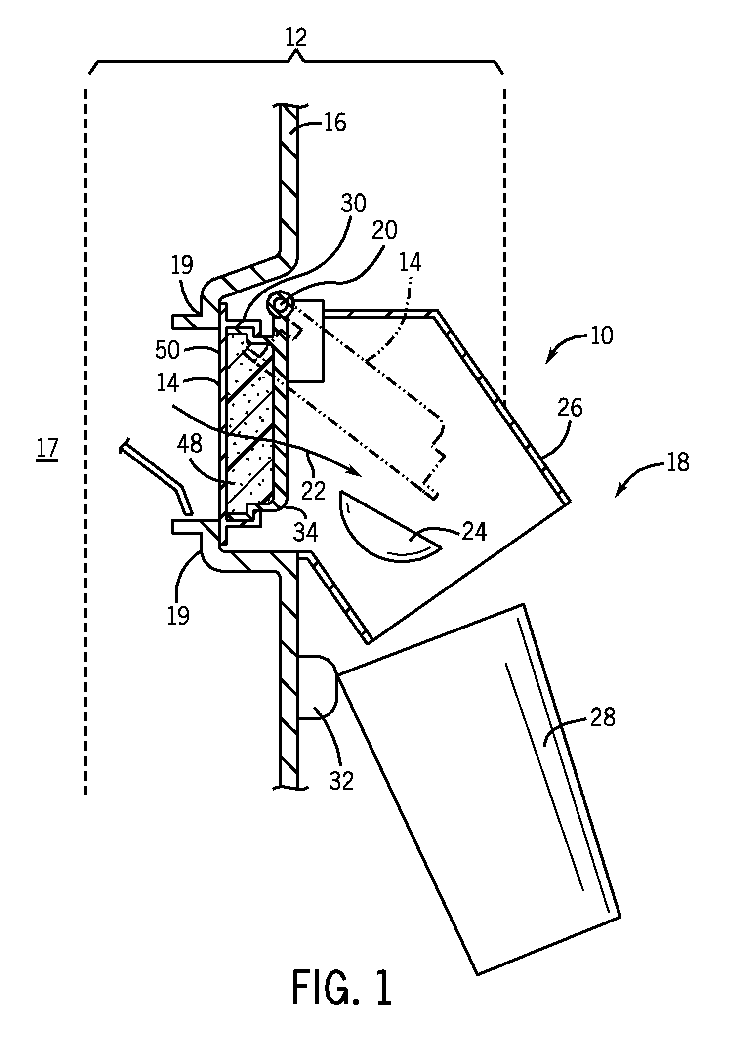
[0033]Referring now to FIG. 1, an ice cube dispensing mechanism 10 per the present invention may fit inside a refrigerator door 12 or the like to provide a pivoting dispenser door 14 on a divider wall 16, the divider wall 16 separating a refrigerated volume 17 of a refrigerator from outside air 18.

[0034]The dispenser door 14 may pivot about an axis 20 to cover or uncover an opening 19 through the divider wall 16 and, in the open position, to provide an unobstructed path 22 for ice cubes 24 to pass down a chute 26 into a glass 28 or the like. Activation of the door 14 to pivot about axis 20 may be provided by a rotary actuator 30 controlled, for example, by electrical dispenser switch 32 operated by a lip of the glass 28.

[0035]Referring now to FIGS. 1 and 2, the door 14 may include a rigid flapper 34 pivoting about an axle 36 extending along the axis 20 and engaging in one direction with an output shaft 35 of the rotary actuator 30. The axle 36 may be retained in journals 40 in a fra...


PUM


Abstract

A rotary actuator suitable for use in a refrigerator ice-dispensing door provides a rotating shaft driven by a DC permanent magnet motor through a gear train and subject to a returning force of an internal spring. The gear train communicates with a switch to reduce current to the motor when a limit of travel is reached and a shunting path is provided around the motor to produce generative braking when power is removed from the motor and the actuator rotates backward to its initial position.

Description

CROSS-REFERENCE TO RELATED APPLICATIONS[0001]This application is National Phase of PCT / US2012 / 046689 filed Jul. 13, 2012 and claims the benefit of U.S. provisional application 61 / 508,345 filed Jul. 15, 2011 and hereby incorporated by reference.FIELD OF THE INVENTION[0002]The present invention relates to a compact rotary actuator and in particular to an electrically actuated door through which ice cubes may be dispensed, using such an actuator.BACKGROUND OF THE INVENTION[0003]Consumer refrigerators may have ice dispensers that dispense ice through an opening in a freezer compartment door. Typically, the opening in the freezer door includes a dispenser door that automatically opens and closes to restrict the entry of ambient air into the freezer compartment.[0004]The dispenser door is normally held closed by a bias spring. When ice is requested by the user, the dispenser door is opened, typically by a solenoid triggered by a switch. The switch may be positioned near the dispenser door...

Claims


Application Information

Patent Timeline
Patent Type & Authority Patents(United States)
IPC IPC(8): H02K7/116H02K26/00H02K7/10H02K7/106H02K11/00F25C5/00F16K1/16
CPCH02K7/116F16K1/16H02K7/106H02K11/0068H02K7/10H02K26/00F25C5/005F25C5/22H02K11/30
Inventor HAPKE, KENYON, A.
Owner ILLINOIS TOOL WORKS INC
Learn More