Quadrant change control in brushless DC motors

a brushless dc motor and quadrant change technology, applied in the field of electric motors, can solve the problems of drawbacks of existing methods for modulating the current in the motor windings of brushless dc motors

Active Publication Date: 2015-05-19
THE BOEING CO
View PDF5 Cites 7 Cited by
  • Summary
  • Abstract
  • Description
  • Claims
  • Application Information

AI Technical Summary

Problems solved by technology

However, existing methods for modulating the current in the motor windings of a brushless DC motor have drawbacks.

Method used


Image

  • Quadrant change control in brushless DC motors
  • Quadrant change control in brushless DC motors
  • Quadrant change control in brushless DC motors

Examples


Embodiment Construction

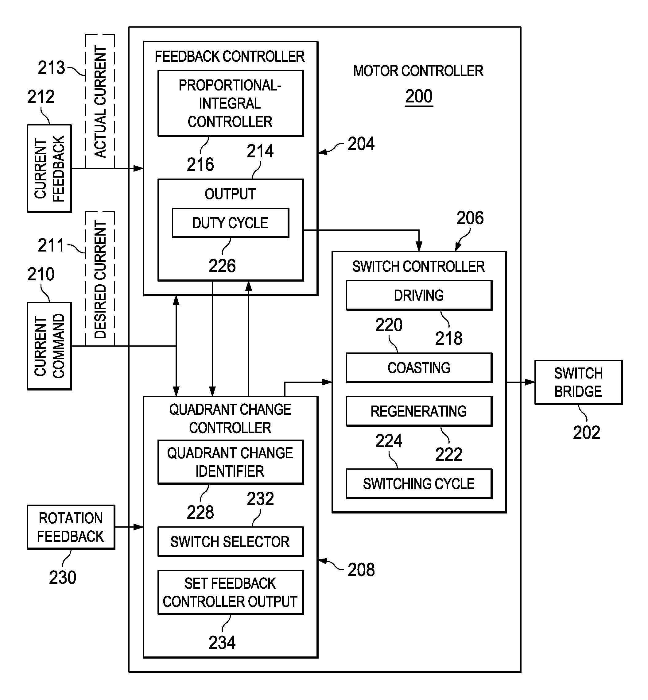
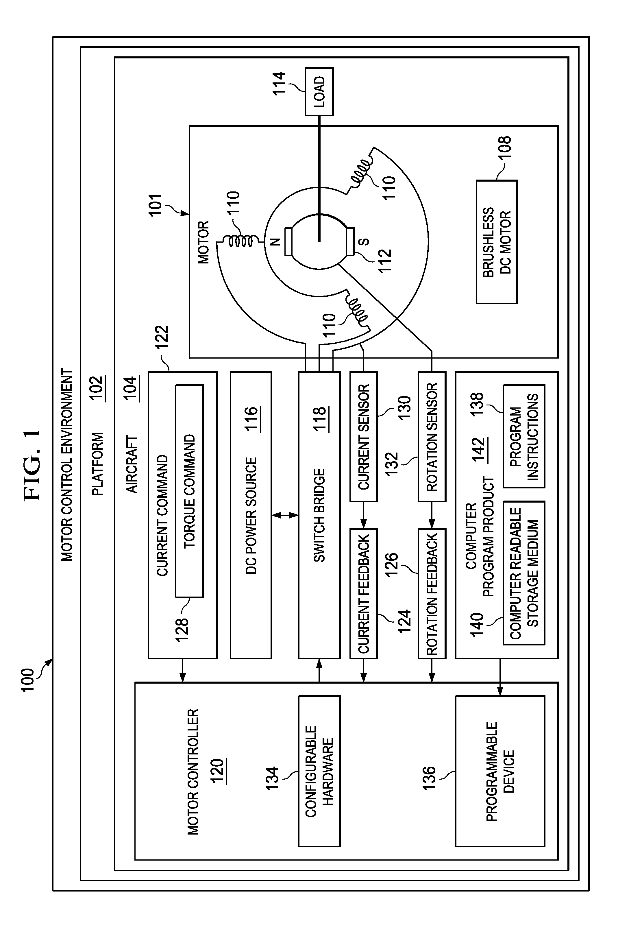
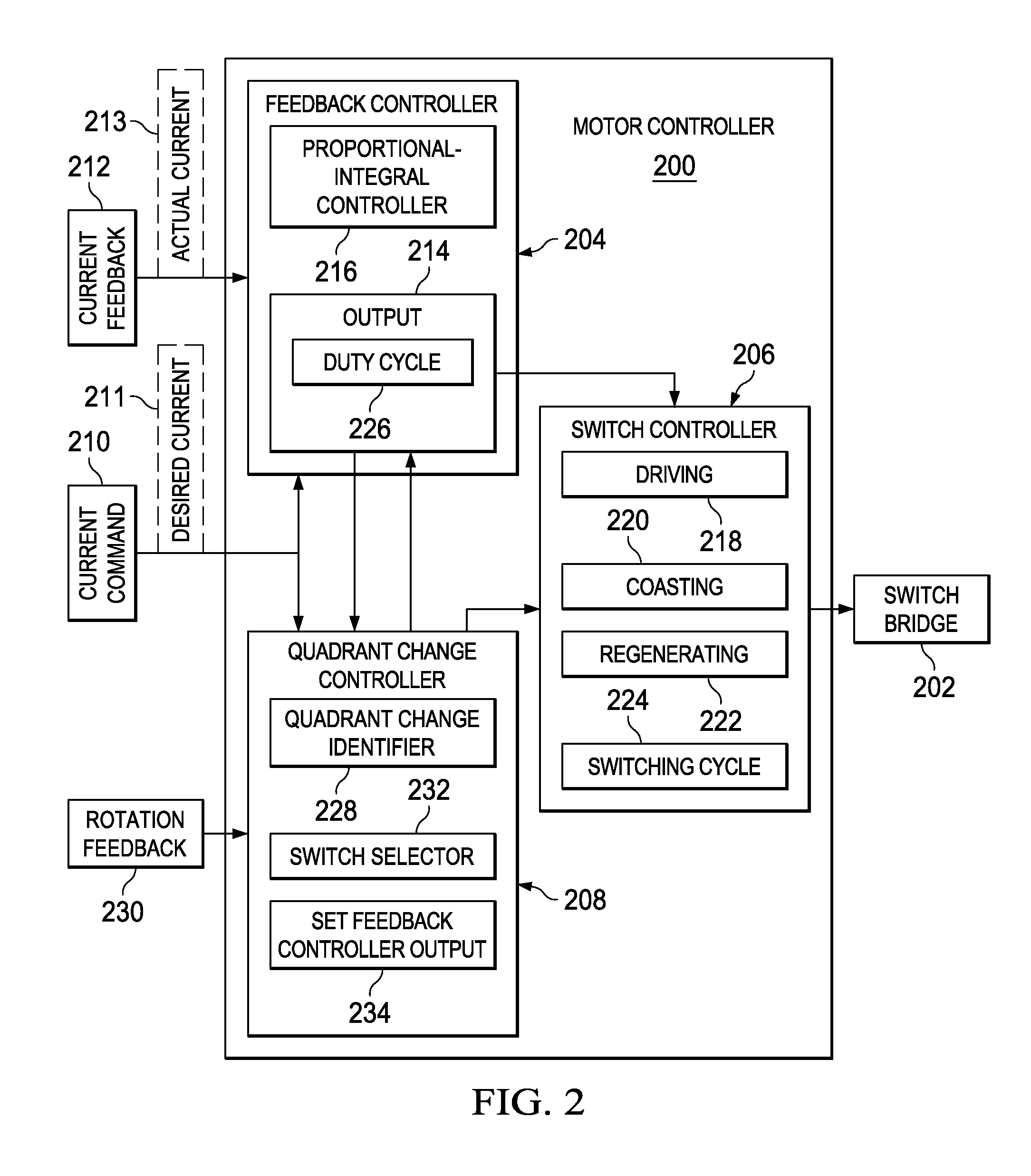
[0035]The different illustrative embodiments recognize and take into account a number of different considerations. “A number”, as used herein with reference to items, means one or more items. For example, “a number of different considerations” means one or more different considerations.

[0036]The different illustrative embodiments recognize and take into account that there are several existing methods to control current via switching modulation in motor windings. However, all of these existing methods may have drawbacks.

[0037]The different illustrative embodiments recognize and take into account that pulse width modulation (PWM) is often used to control the current in motor windings. However, motor current controlled using pulse width modulation suffers ripple currents during all operations, even quiescent operations. With pulse width modulation, a zero current command results in a ripple current. Depending upon the inductance, power supply, and duty cycle frequency, the ripple curre...


PUM


Abstract

A method and apparatus for controlling a change in a quadrant of operation of a brushless direct current motor. A quadrant change in an operation of a motor is identified. In response to identifying the quadrant change, selected ones of a plurality of switches in a switch bridge are selected to be controlled to couple a direct current power source to the windings of the motor to change a direction of an actual current in the windings.

Description

BACKGROUND INFORMATION[0001]1. Field[0002]The present disclosure relates generally to electric motors, such as brushless direct current (DC) motors, and to the control of such electric motors. More particularly, the present disclosure relates to controlling a brushless DC motor to change between different quadrants of operation.[0003]2. Background[0004]Aircraft may employ various electronic devices and systems to perform various functions on the aircraft. For example, without limitation, electric motors on an aircraft may be used to move flight control surfaces, to raise and lower landing gear, and to perform other functions on the aircraft. Power for the electric motors and other electronic systems and devices on an aircraft may be provided by an aircraft power system.[0005]An example of a type of electric motor used on aircraft, and for many other applications, is a brushless DC electric motor. These types of motors are also known as electronically commutated motors. Brushless DC ...

Claims


Application Information

Patent Timeline
Patent Type & Authority Patents(United States)
IPC IPC(8): H02P1/04H02P6/00
CPCH02P6/003H02P6/085H02M7/53871H02M7/5395H02M7/797H02P6/30H02P25/03H02P25/034B60L15/007B60L15/02B60L2220/20B60L2240/423B60L2240/429B60L50/11Y02T10/64Y02T10/7072Y02T10/70
Inventor CAMERON, DOUGLAS C.
Owner THE BOEING CO
Why Eureka
Try Eureka