Power supply circuitry and current measurement

a power supply circuit and current measurement technology, applied in the direction of electric variable regulation, process and machine control, instruments, etc., can solve the problems of reducing the reliability of the circuit, and reducing the conversion efficiency of the power supply, so as to achieve the effect of higher conversion efficiency

Active Publication Date: 2015-05-19
INFINEON TECH AMERICAS CORP
View PDF12 Cites 31 Cited by
  • Summary
  • Abstract
  • Description
  • Claims
  • Application Information

AI Technical Summary

Benefits of technology

[0007]Conventional applications such as those as discussed above can suffer from a number of deficiencies. For example, inclusion of a resistor in series with a respective power supply phase is often undesirable because the resistor results in dissipation of heat, reducing the conversion efficiency of the power supply. Moreover, increasing a number of components in a circuit also typically translates into lower circuit reliability. Inclusion of the resistor in a phase, although it may be a rather small component, increases the size of the power supply circuit.
[0018]The embodiments as described herein are advantageous over conventional techniques. For example, the embodiments as discussed herein can utilize existing power supply circuitry without having to dispose an extra resistor in a respective path of a power converter phase to measure a current provided by the power converter phase. Measurement of current in a power converter phase without having to add an extra resistor as in conventional circuits results in higher conversion efficiency. That is, more of the power inputted to a power converter phase is conveyed and dissipated in a load as opposed to being dissipated in the power converter phase when in-line resistor is not implemented.

Problems solved by technology

Conventional applications such as those as discussed above can suffer from a number of deficiencies.
For example, inclusion of a resistor in series with a respective power supply phase is often undesirable because the resistor results in dissipation of heat, reducing the conversion efficiency of the power supply.
Moreover, increasing a number of components in a circuit also typically translates into lower circuit reliability.
Inclusion of the resistor in a phase, although it may be a rather small component, increases the size of the power supply circuit.
Additionally, DCR current sensing can be inaccurate due to fast switching frequencies in which parasitics arise or when the inductor coil heats-up.
Both conditions can affect the tuned circuit network, rendering the conventional current sense measurement less accurate.
Furthermore, conventional DCR current sensing typically requires low pass filtering and may require additional pins on a chip device to implement.

Method used


Image

  • Power supply circuitry and current measurement
  • Power supply circuitry and current measurement
  • Power supply circuitry and current measurement

Examples


Embodiment Construction

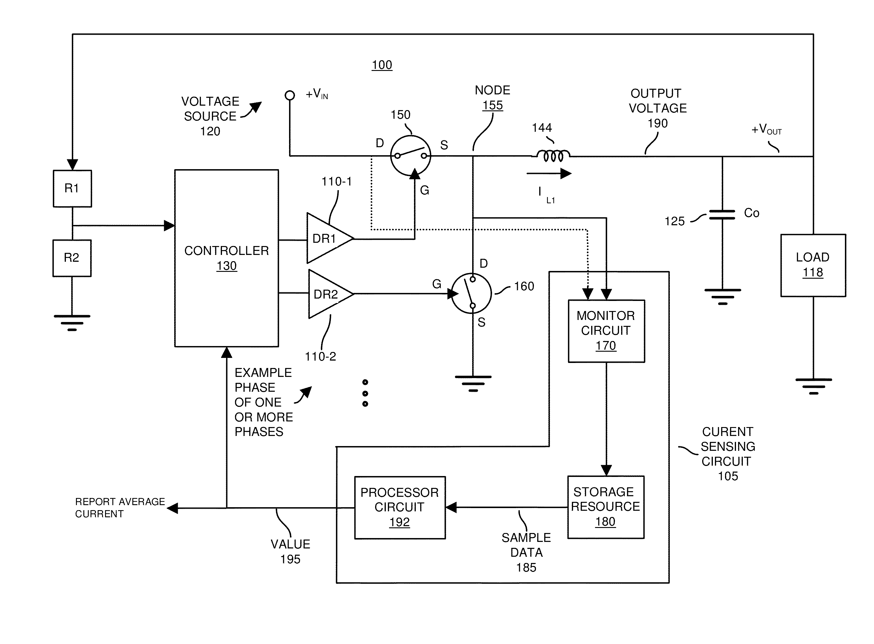
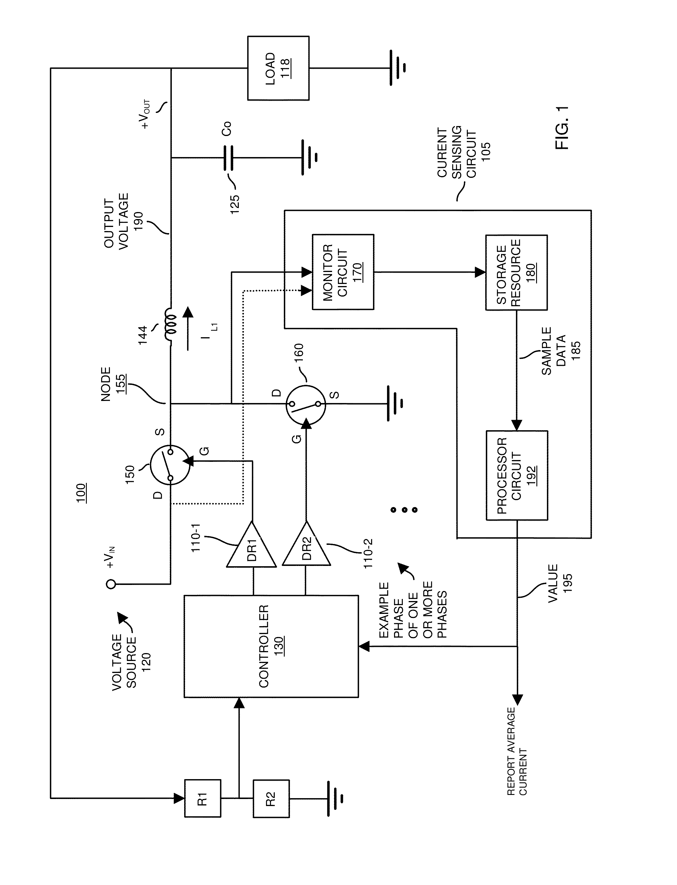
[0035]Embodiments herein include novel ways of measuring current in a switching power supply circuit. For example, in accordance with one embodiment, a power supply circuit includes an inductor, a monitor circuit, a storage resource, and a processor circuit. The inductor resides in a phase of the power supply and conveys current to a load. The monitor circuit monitors and samples the voltage of a node in the power supply. The voltage of the node may be a sawtooth or ramp waveform sampled by the monitor circuit. A magnitude of the voltage at the node varies depending on an amount of current passing through the inductor to the load. The monitor circuit initiates storage of the samples in a storage resource. A processor circuit utilizes the multiple sample voltages stored in the storage resource to produce a value indicative of the amount of average current conveyed through the inductor to the load.

[0036]More specifically, FIG. 1 is an example diagram of power supply circuit including ...


PUM


Abstract

According to one configuration, a power supply circuit includes an inductor, a monitor circuit, a storage resource, and a processor circuit. The inductor resides in a phase of the power supply and conveys current to a load. The monitor circuit monitors and samples the voltage of a node in the power supply. The voltage of the node may be a sawtooth or ramp waveform sampled by the monitor circuit. A magnitude of the voltage at the node varies depending on an amount of current passing through the inductor to the load. The monitor circuit initiates storage of at least one sample in a storage resource. A processor circuit utilizes the multiple sample voltages stored in the storage resource to produce a value indicative of the amount of average current conveyed through the inductor to the load.

Description

BACKGROUND[0001]An example of a conventional DC-DC converter is a so-called synchronous buck converter. It has minimal components, and therefore is widely used in voltage regulator applications. In an example conventional application, the input voltage to the buck converter is typically 12VDC. An output voltage produced by the buck converter may be 5.0VDC, 3.3 VDC, or even lower.[0002]A typical configuration of a conventional voltage converter includes one or more power converter phases. Each power converter phase can include an inductor, a high side switch (a.k.a., a control switch) and a low side switch (a.k.a., a synchronous switch).[0003]In general, during operation, a control circuitry associated with a conventional voltage converter repeatedly pulses the high side switch ON to convey power from a power source through the one or more inductors in the phases to a dynamic load. The control circuitry repeatedly pulses the low side switch ON (in between switching the high side swit...

Claims


Application Information

Patent Timeline
Patent Type & Authority Patents(United States)
IPC IPC(8): H02M3/157H02M1/00H02M3/156H02M3/158
CPCH02M3/156H02M3/1588H02M2001/0009Y02B70/10H02M1/0009
Inventor RAHIMI, AMIR M.PARTO, PARVIZ
Owner INFINEON TECH AMERICAS CORP
Why Eureka
Try Eureka