
Graphite thermal decontamination with reducing gases

a graphite and thermal decontamination technology, applied in the direction of radioactive decontamination, separation processes, nuclear engineering, etc., can solve the problems of difficult handling of graphite, large reduction or limitation of the amount of carbon-14 removal, and decay after a few tens of years, so as to reduce the size of graphite

Active Publication Date: 2015-05-26
ELECTRICITE DE FRANCE
View PDF1 Cites 5 Cited by
  • Summary
  • Abstract
  • Description
  • Claims
  • Application Information

AI Technical Summary

Benefits of technology

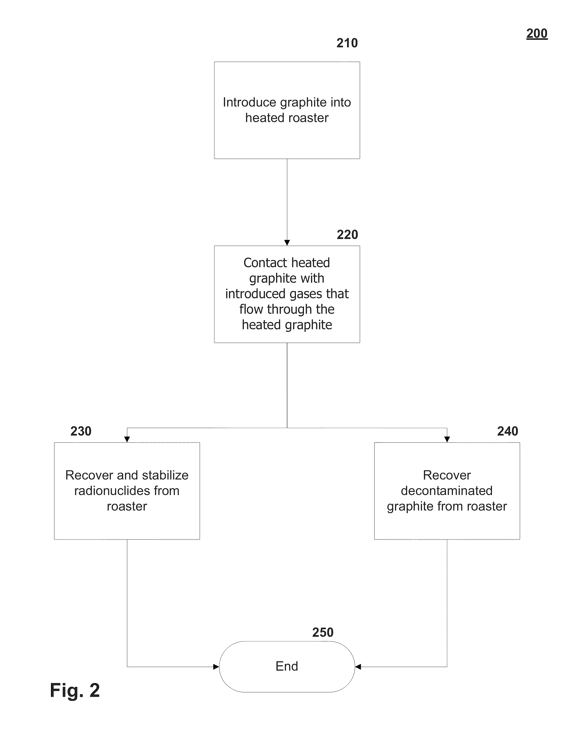
This patent describes a method for subjecting graphite to a high temperature to remove radionuclides without significantly gasifying the graphite. The method involves heating a roaster, introducing contaminated graphite into the roaster, introducing an inert gas, introducing a reducing gas, and removing volatilized radionuclides from the roaster. This method may also include adding an oxidizing gas or reducing the size of the graphite before introducing it into the roaster. The purge gas and reducing gas can produce hydrogen or organic vapor. The oxidizing gas can include steam, carbon dioxide, nitrous oxide, or other oxygenated vapors. The method can be carried out in a vertically-oriented moving bed reactor, with the steps of introducing the gases near the bottom or top of the reactor. The technical effect of this method is that it allows for the efficient removal of radionuclides from contaminated graphite without significantly altering its shape or size.

Problems solved by technology

Short-lived isotopes (such as cobalt-60) make the graphite difficult to handle immediately after reactor shutdown, but they decay after a few tens of years.
Unfortunately, by reducing or limiting the roasting temperature, the amount of carbon-14 removal is also greatly reduced or limited.
Still, when roasting temperatures exceed approximately 1200° Celsius, the amount of bulk graphite gasified is excessive regardless of the reduced concentration of oxygen containing gases that are used.
In either case, an objective of volatilizing more than ninety (90) percent of the carbon-14 while simultaneously reducing bulk graphite gasification to less than five (5) percent by weight cannot be achieved with these conventional methods.

Method used


Image

  • Graphite thermal decontamination with reducing gases
  • Graphite thermal decontamination with reducing gases
  • Graphite thermal decontamination with reducing gases

Examples


Embodiment Construction

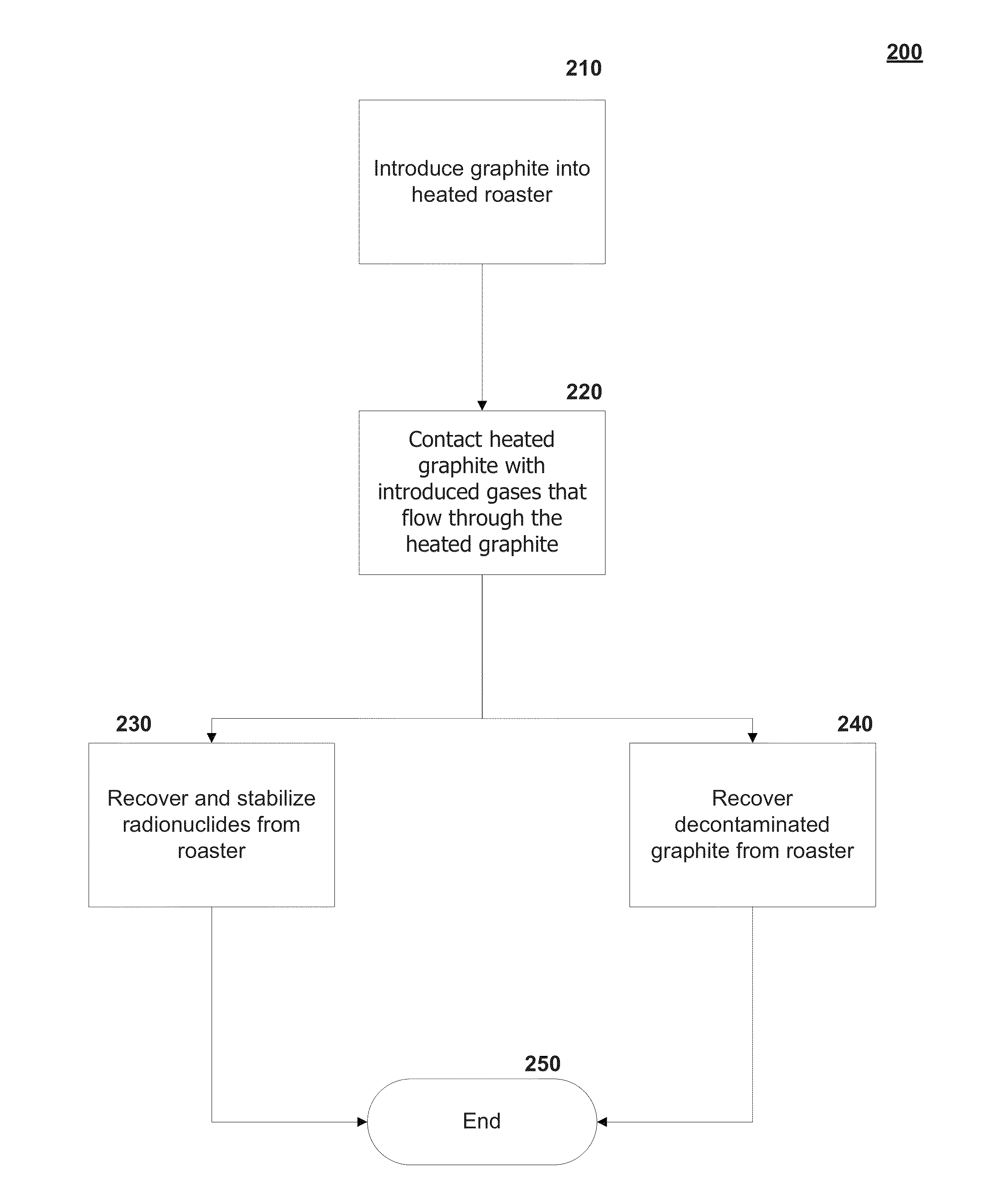
[0024]The exemplary embodiments of the present invention provide systems and methods for treating radioactive graphite contaminated with tritium, carbon-14, and chlorine-36 and other radionuclides generated during the operation of a nuclear reactor or other nuclear process. The systems and methods include a roaster that operates at temperatures in the range of 800° Celsius to 2000° Celsius with inert, optional oxidizing and reducing gases. The combination of temperatures and gases allow for the removal of greater than 90 percent of the carbon-14 within the graphite while gasifying less than 5 percent of the bulk graphite.

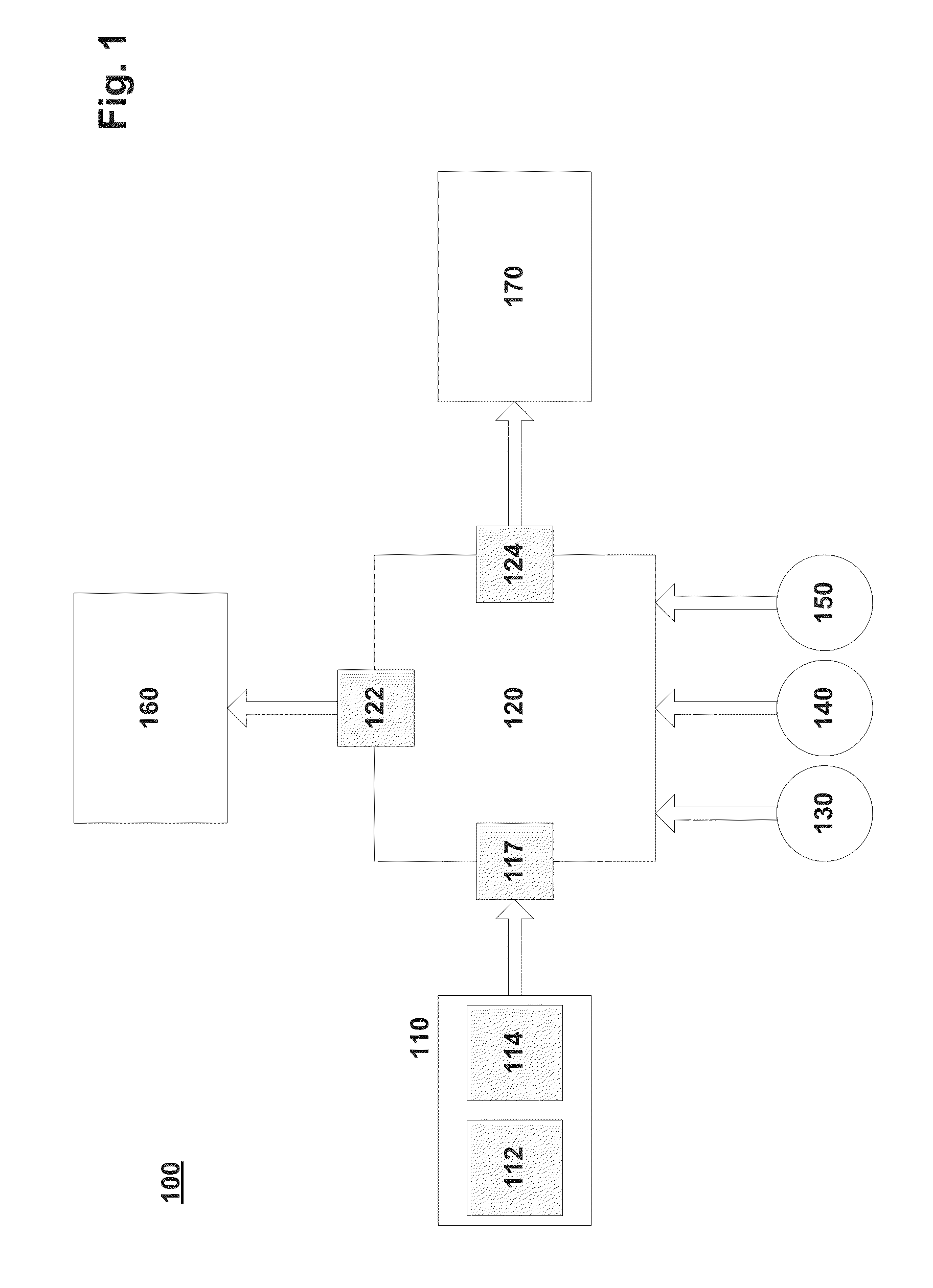
[0025]FIG. 1 depicts a block diagram of a system 100 for treating radioactive graphite in accordance with an exemplary embodiment of the present invention. Referring to FIG. 1, a materials handling component 110 receives graphite to be treated in the system 100. Typically, the graphite was used as the moderator in a nuclear reactor core. Other sources of graphite in...


PUM

PropertyMeasurementUnit
sizeaaaaaaaaaa
temperatureaaaaaaaaaa
sizeaaaaaaaaaa

Abstract

Providing a roaster that operates at temperatures in the range of 800° Celsius to 2000° Celsius with inert, optional oxidizing and reducing gases to treat graphite contaminated with radionuclides including tritium, carbon-14, and chlorine-36. The combination of temperatures and gases allow for the removal of most to substantially all the carbon-14 within the graphite while substantially limiting gasifying the bulk graphite.

Description

TECHNICAL FIELD[0001]The present invention relates generally to methods for decontamination of graphite to remove tritium, carbon-14, and chlorine-36 using thermal treatment with purge gases that include reducing gases.BACKGROUND[0002]Graphite, which consists predominantly of the element carbon, is used as a moderator in a number of nuclear reactor designs, such as the MAGNOX and AGR gas cooled reactors in the United Kingdom, and the RBMK design in Russia. During construction, the moderator of the reactor is usually installed as an interlocking structure of graphite bricks. At the end of reactor life, the graphite moderator, typically weighing about 2,000 tons, is a form of radioactive waste that requires safe disposal. Graphite is a relatively stable chemical form of carbon, which is in many ways suitable for direct disposal without processing. However, after neutron irradiation, the graphite will contain stored Wigner energy. The potential for release of this energy needs to be ac...

Claims


Application Information

Patent Timeline
Patent Type & Authority Patents(United States)
IPC IPC(8): C01B31/04B01D59/02G21F9/02G21F9/30
CPCB01D59/02G21F9/30G21F9/02G21F9/007G21F9/28G21F9/32
Inventor MASON, J. BRADLEYBROWN, THOMASTORABZADEH, SAHAROLANDER, JONATHAN
Owner ELECTRICITE DE FRANCE
Learn More