Precise targeting of surgical photodisruption

Active Publication Date: 2015-06-02
ALCON INC
View PDF311 Cites 15 Cited by
  • Summary
  • Abstract
  • Description
  • Claims
  • Application Information

AI Technical Summary

Benefits of technology

[0013]In another aspect, a laser system for performing laser surgery on the eye includes a control system; a laser source emitting a laser beam for surgically affecting the tissue of an eye under a control of the control system; an optical coherence tomography (OCT) imaging system a control of the control system to produce a probe light beam that optically gathers information on an internal structure of the eye; an attachment mechanism structured to fix the surface of the eye in position and to provide reference in three dimensional space relative to the OCT imaging system; a mechanism to supply the control system with positional information on the internal structure of the eye derived from the OCT imaging system; and an optical unit that focuses the laser beam controlled by the control system into the eye for surgical treatment.
[0014]In another aspect, An imaging-guided laser surgical system includes a surgical laser that produces a surgical laser beam of surgical laser pulses that cause surgical changes in a target tissue under surgery; a patient interface mount that engages a patient interface in contact with the target tissue to hold the target tissue in position; a laser beam delivery module located between the surgical laser and the patient interface and configured to direct the surgical laser beam to the target tissue through the patient interface, the laser beam delivery module operable to scan the surgical laser beam in the target tissue along a predetermined surgical pattern; a laser control module that controls operation of the surgical laser and controls the laser beam delivery module to produce the predetermined surgical pattern; and an optical coherence tomography (OCT) module positioned relative to the patient interface to have a known spatial relation with respect to the patient interface and the target issue fixed to the patient interface. The OCT module is configured to direct an optical probe beam to the target tissue and receive returned probe light of the optical probe beam from the target tissue to capture OCT images of the target tissue while the surgical laser beam is being directed to the target tissue to perform an surgical operation so that the optical probe beam and the sur

Problems solved by technology

Recent development of laser surgical methods for performing operations on the human eye, such as LASIK combined with flap creation using a femtosecond laser,

Method used


Image

  • Precise targeting of surgical photodisruption
  • Precise targeting of surgical photodisruption
  • Precise targeting of surgical photodisruption

Examples


Example

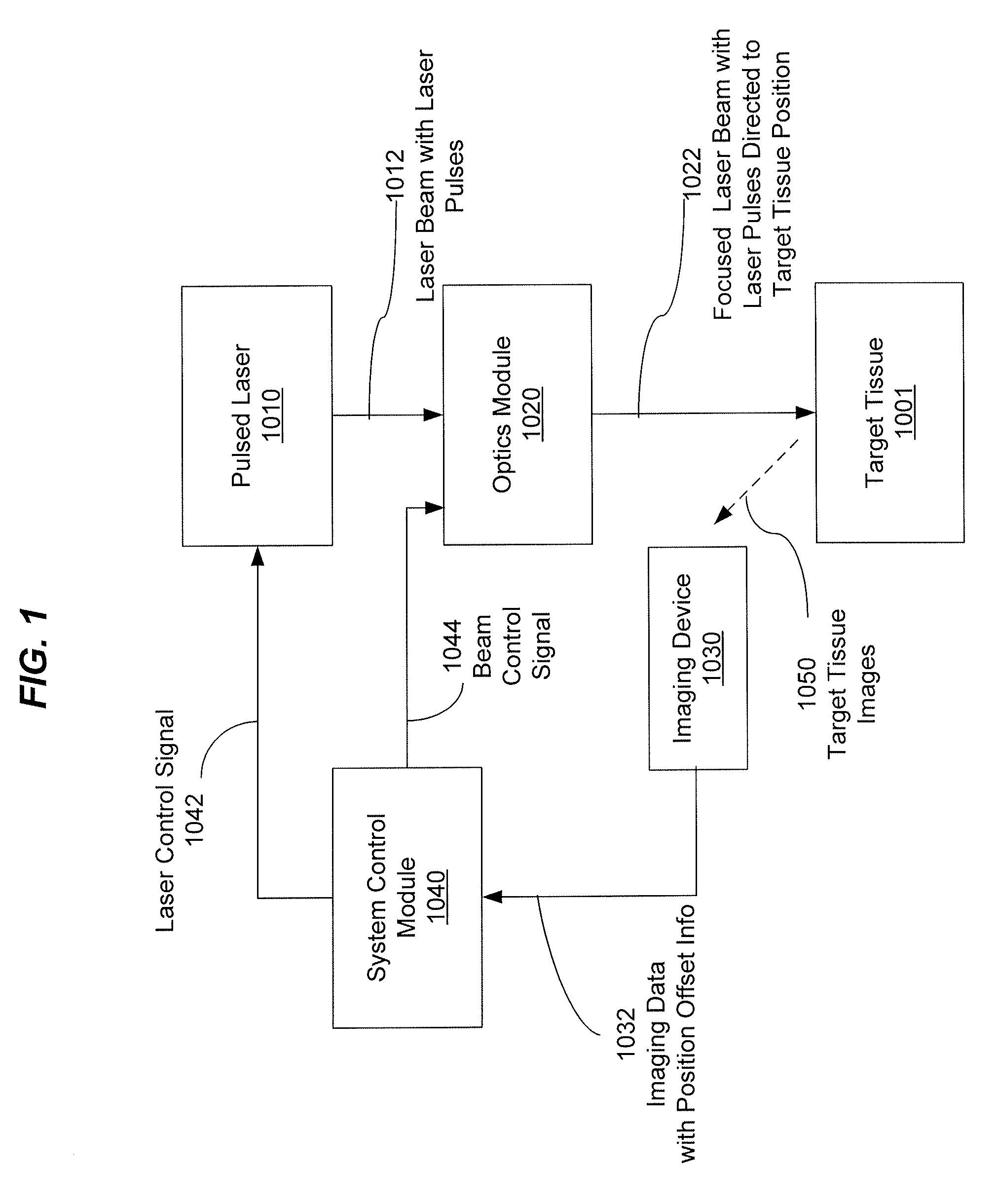
[0032]One important aspect of laser surgical procedures is precise control and aiming of a laser beam, e.g., the beam position and beam focusing. Laser surgery systems can be designed to include laser control and aiming tools to precisely target laser pulses to a particular target inside the tissue. In various nanosecond photodisruptive laser surgical systems, such as the Nd:YAG laser systems, the required level of targeting precision is relatively low. This is in part because the laser energy used is relatively high and thus the affected tissue area is also relatively large, often covering an impacted area with a dimension in the hundreds of microns. The time between laser pulses in such systems tend to be long and manual controlled targeting is feasible and is commonly used. One example of such manual targeting mechanisms is a biomicroscope to visualize the target tissue in combination with a secondary laser source used as an aiming beam. The surgeon manually moves the focus of a ...


PUM


Abstract

Techniques, apparatus and systems for laser surgery including imaging-guided surgery techniques, apparatus and systems.

Description

PRIORITY CLAIM AND RELATED PATENT APPLICATION[0001]This patent document is a continuation of co-pending U.S. patent application Ser. No. 12 / 205,844, filed on Sep. 5, 2008, entitled “Precise Targeting of Surgical Photodisruption” by R. M. Kurtz, F. Raksi and M. Karavitis, that claims priority from and benefit of U.S. Patent Application No. 60 / 970,477, filed on Sep. 6, 2007, entitled “Precise Targeting of Surgical Photodisruption” by R. M. Kurtz, F. Raksi and M. Karavitis, both patent applications incorporated herein in their entirety by reference as part of the specification of the present patent document.BACKGROUND[0002]This document relates to laser surgery techniques, apparatus and systems, including laser surgery techniques, apparatus and systems based on photodisruption caused by laser pulses in a tissue.[0003]Laser light can be used to perform various surgical operations in eyes and other tissues in humans and animals. Recent development of laser surgical methods for performing...

Claims


Application Information

Patent Timeline
IPC IPC(8): A61F9/008A61B5/00A61B17/00A61B18/20A61B19/00A61F9/009
CPCA61F9/00825A61B18/20A61B5/0066A61B2017/00057A61B2019/5276A61B2019/5437A61B2560/0233A61F9/009A61F2009/00844A61F2009/0087A61F2009/00872A61F2009/00897A61B2090/378A61B2090/3937A61F9/0084A61F2009/00851A61F2009/00882A61F2009/0088
Inventor KURTZ, RONALD M.RAKSI, FERENCKARAVITIS, MICHAEL
Owner ALCON INC
Why Eureka
Try Eureka