Elevator rope sway estimation

a technology of elevator rope and sway, which is applied in the direction of elevators, instruments, transportation and packaging, etc., can solve the problems of affecting the operation of the elevator system, so as to achieve the effect of minimizing the cost function

Inactive Publication Date: 2015-06-02
MITSUBISHI ELECTRIC RES LAB INC
View PDF20 Cites 6 Cited by
  • Summary
  • Abstract
  • Description
  • Claims
  • Application Information

AI Technical Summary

Benefits of technology

[0011]Typically, the sway of the elevator rope is determined between two boundaries. For example, the elevator rope connects an elevator car with a pulley, and one embodiment measures the sway of the elevator rope between corresponding connections of the rope with the elevator car and the pulley. Therefore, in one embodiment, two boundary sensors are arranged into the elevator system, and incorporated in the model of the elevator system. For example, a first boundary sensor is configured to measure a lateral motion of the elevator car, and a second boundary sensor is configured to measure a lateral motion of the pulley. This embodiment determines a position of the sensor, i.e., a sway sensor, by interpolation of locations measured by the boundary sensors and a location of the point that optimizes the error, e.g., minimizes the error.
[0018]Another embodiment formulates a cost function of a time of the simulation, a length of the elevator rope between the first boundary sensor and the second boundary sensor, the error, and a function of conditions of disturbance, and determines the sway location, such that a result of the cost function is minimized.

Problems solved by technology

The oscillation can be a significant problem in a roped elevator system.
If the elevator system use multiple ropes and the ropes oscillate out of phase with one another, then the ropes can become tangled with each other and the elevator system may be damaged.
However, a mechanical device attached to a compensating rope is difficult to install and maintain.
This method is general and may not provide precise estimation of the rope sway.

Method used


Image

  • Elevator rope sway estimation
  • Elevator rope sway estimation
  • Elevator rope sway estimation

Examples


Embodiment Construction

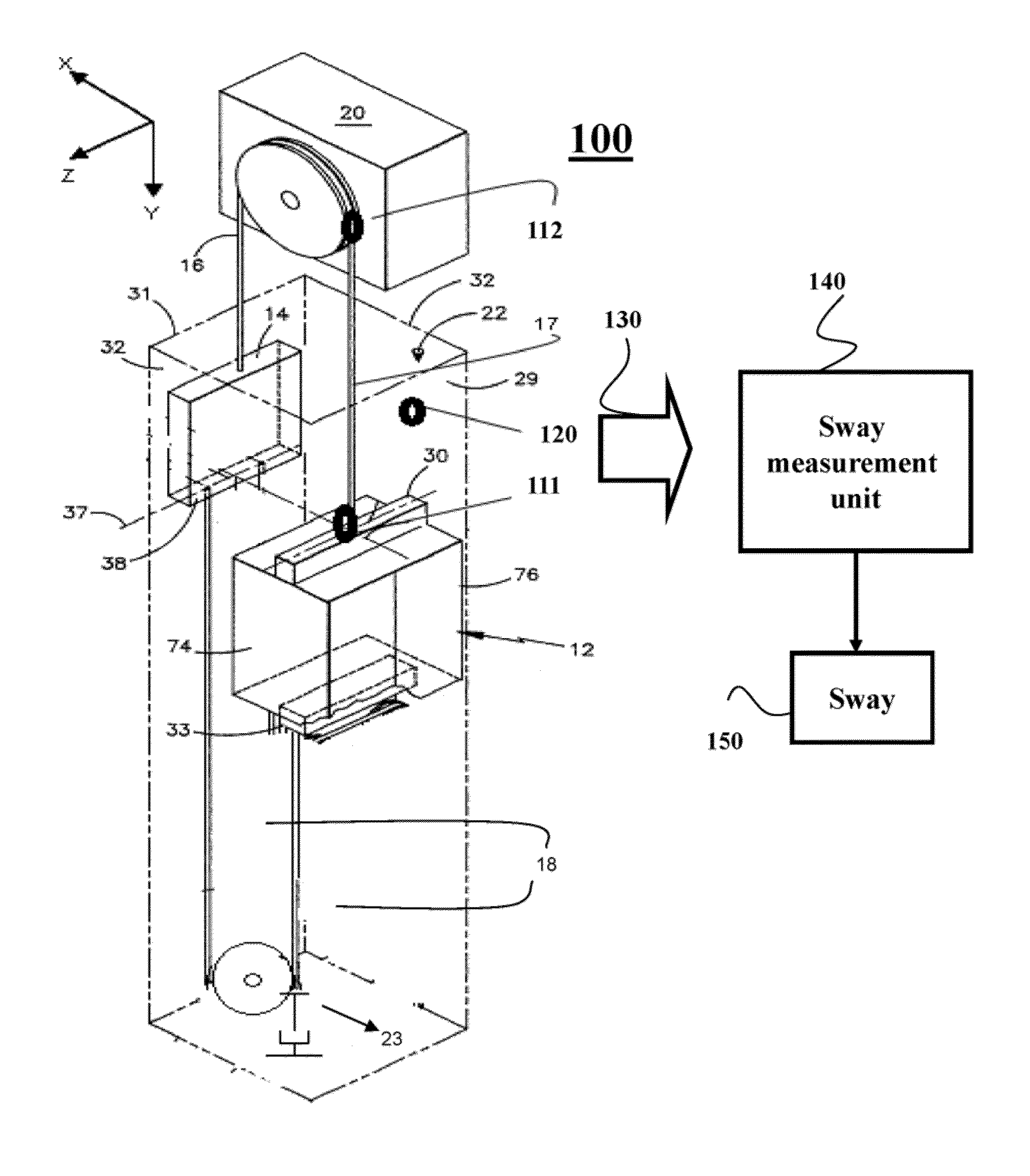
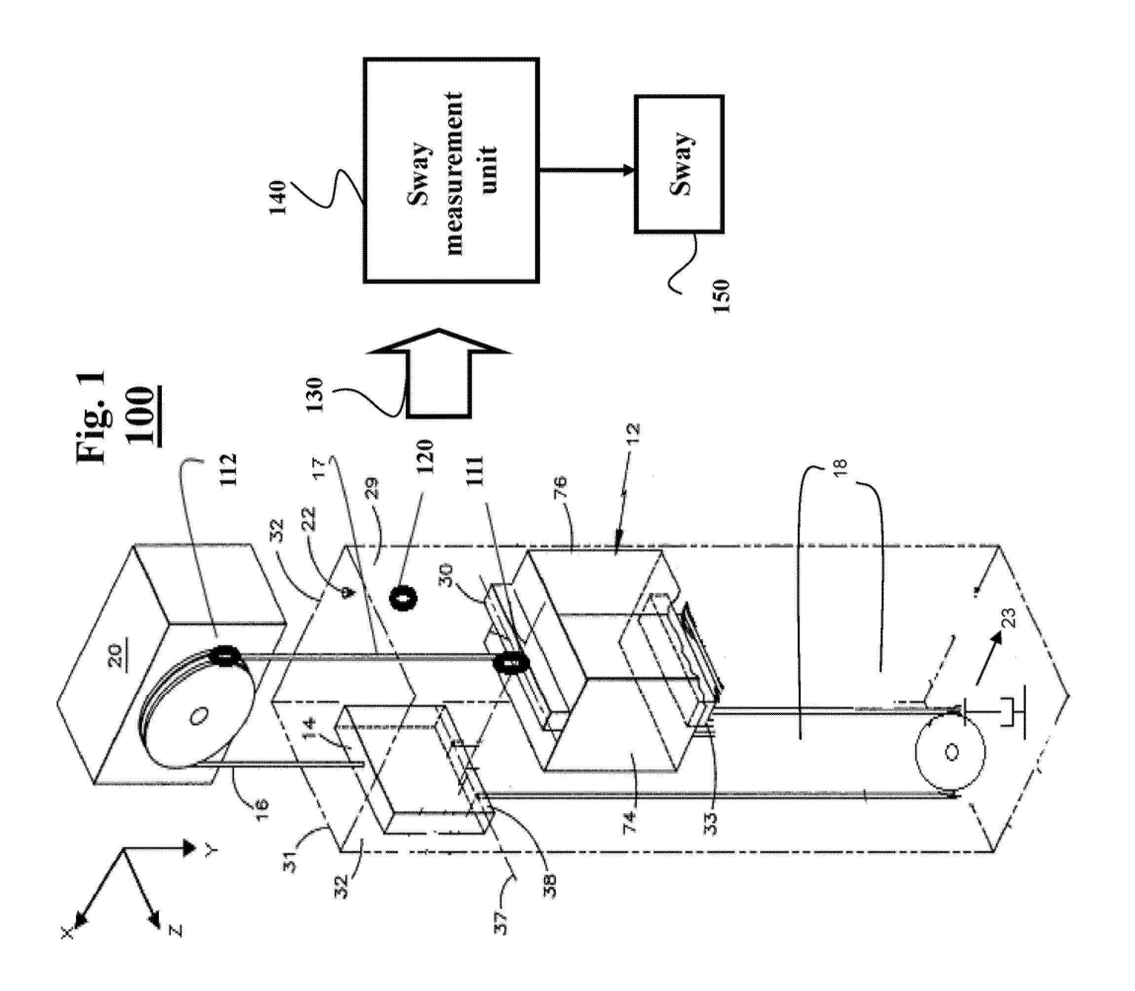
[0039]FIG. 1 shows an example elevator system 100 according to one embodiment of an invention. The elevator system includes an elevator car 12 connected by at least one elevator rope to different components of the elevator system. For example, the elevator car and a counterweight 14 attached to one another by main ropes 16-17, and compensating ropes 18. The elevator car 12 can include a crosshead 30 and a safety plank 33, as known in the art. A pulley 20 for moving the elevator car 12 and the counterweight 14 through an elevator shaft 22 can be located in a machine room (not shown) at the top (or bottom) of the elevator shaft 22. The elevator system can also include a compensating pulley 23. An elevator shaft 22 includes a front wall 29, a back wall 31, and a pair of side walls 32.

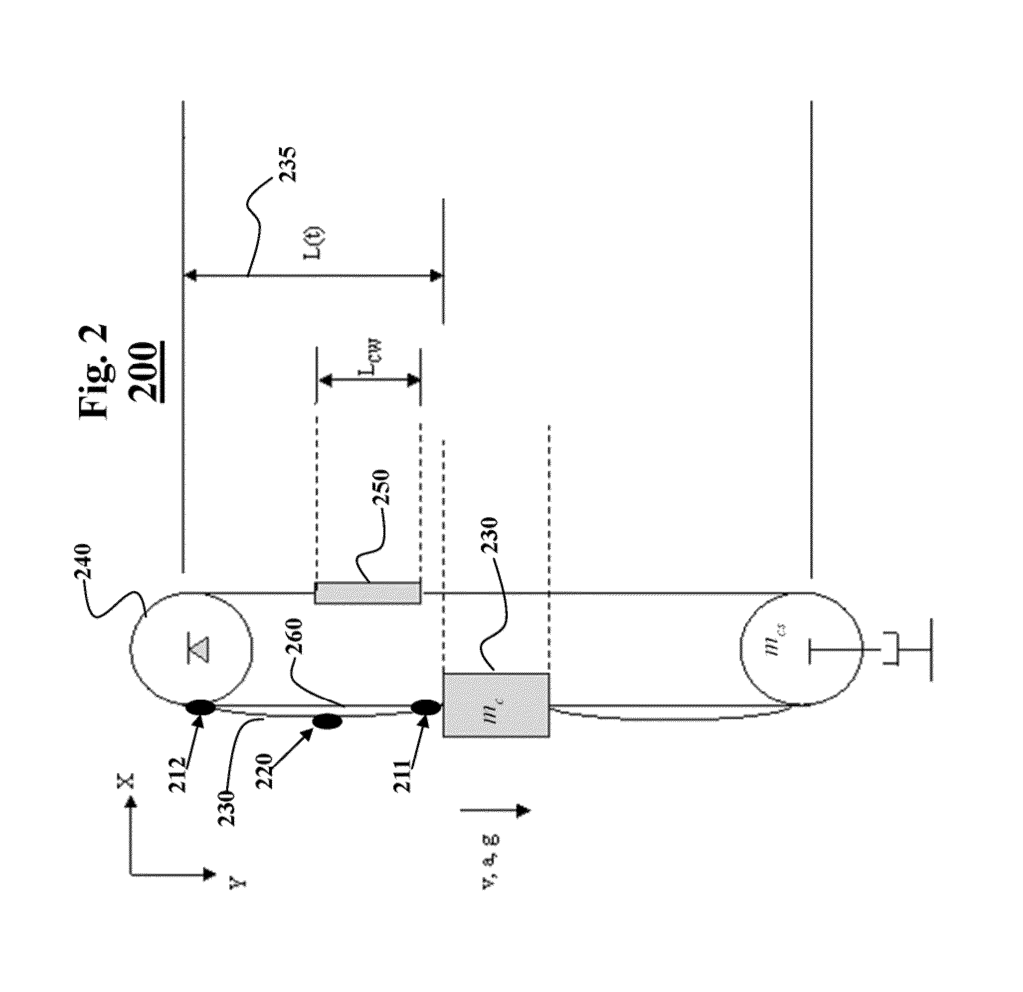
[0040]The elevator car and the counterweight can have a center of gravity which is defined as a point at which the summations of the moments in the x, y, and z directions about that point equal zero. In ot...


PUM


Abstract

A method and a system determine a position of at least one sway sensor in an elevator system for sensing a lateral motion of an elevator rope between a first boundary location and a second boundary location. An operation of the elevator system is simulated with a model of the elevator system to produce an actual shape of the elevator rope caused by the operation. At least one sway location is determined, such that an error between the actual shape of the elevator rope and an estimated shape of the elevator rope is minimized. The estimated shape of the elevator rope is determined by interpolation of the first boundary location, the second boundary location, and the sway location. The position of the sway sensor is determined, such that the sway sensor senses the lateral motion of the elevator rope at the sway location.

Description

FIELD OF THE INVENTION[0001]This invention relates generally to elevator systems, and more particularly to measuring a sway of an elevator rope of an elevator system.BACKGROUND OF THE INVENTION[0002]Typical elevator systems include a car and a counterweight confined to travel along guiderails in a vertically extending elevator shaft. The car and the counterweight are connected to each other by hoist ropes. The hoist ropes are wrapped around a sheave located in a machine room at the top (or bottom) of the elevator shaft. In conventional elevator systems, the sheave is powered by an electrical motor. In other elevator systems, the sheave is unpowered, and the drive means is a linear motor mounted on the counterweight.[0003]Rope sway refers to oscillation of the hoist and / or compensation ropes in the elevator shaft. The oscillation can be a significant problem in a roped elevator system. The oscillation can be caused, for example, by vibration emanating from wind induced building defle...

Claims


Application Information

Patent Timeline
Patent Type & Authority Patents(United States)
IPC IPC(8): G01C9/00G01C17/00G01C19/00B66B7/06
CPCB66B7/06
Inventor BENOSMAN, MOUHACINEBORTOFF, SCOTT A.
Owner MITSUBISHI ELECTRIC RES LAB INC
Why Eureka
Try Eureka