High-speed railroad inspection using coordinated 3D cameras

a high-speed railroad and 3d camera technology, applied in the field of depth inspection, can solve the problems of time-consuming tactile approaches, laborious and long interpretation of charts and maps, and data transmission, and achieve the effect of accurately calculating the depth of certain objects

Inactive Publication Date: 2015-06-02
PRINCE JOHN H
View PDF16 Cites 77 Cited by
  • Summary
  • Abstract
  • Description
  • Claims
  • Application Information

AI Technical Summary

Benefits of technology

[0013]In addition to viewing (particularly) the ties as flat the software can accurately calculate the depth of certain anomalies, as will be shown.

Problems solved by technology

Because rail inspection has traditionally been done by “walking the tracks”—which is to say by a person carrying a notepad and visually assessing such items as missing bolts and damaged rails, it has been slow.
However the transfer of data, the interpretation on charts and maps, can still be laborious and lengthy.
There are also time-consuming tactile approaches.
In the present instance such specular surfaces do not obtain from rails or ties for the creation of 3D images.
Laser scanning is also computationally expensive and reconstruction to create 3D images is lengthy.
A single track failure can be catastrophic for passengers, goods, equipment and environment.
It is no longer thinkable to do any part of this by “walking the tracks” or even by running slow-moving trucks that can interfere with rail traffic.

Method used


Image

  • High-speed railroad inspection using coordinated 3D cameras
  • High-speed railroad inspection using coordinated 3D cameras
  • High-speed railroad inspection using coordinated 3D cameras

Examples


Embodiment Construction

[0025]In order to emulate the depth-perception and 3D acuity of pairs of human eyes, the cameras come as pairs with highly compact electronics integral to their function. Two cameras forming each pair are separated by a distance determined by their application and work as a single unit. Each unit is adapted to its specific role (as described below).

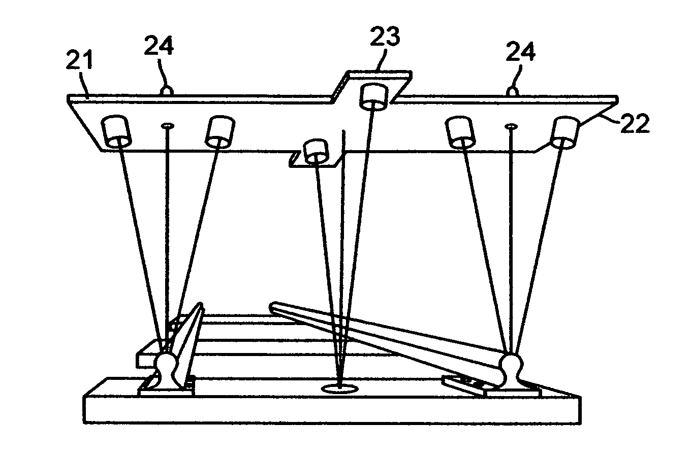
[0026]FIG. 1 shows a bilaterally symmetrical structure 21 for holding three sets (pairs) of cameras, or six cameras. This consists of a transverse member 22 and a longitudinal member 23 of sufficient stiffness and damping to hold the three sets of cameras rigid and resonance-free when mounted. Two projections 24 are bolts or clamps for mounting the structure onto a suitable railcar. For standard gauge tracks the length of transverse member 22 is about 84″ and the length of longitudinal member 23 is about 24″.

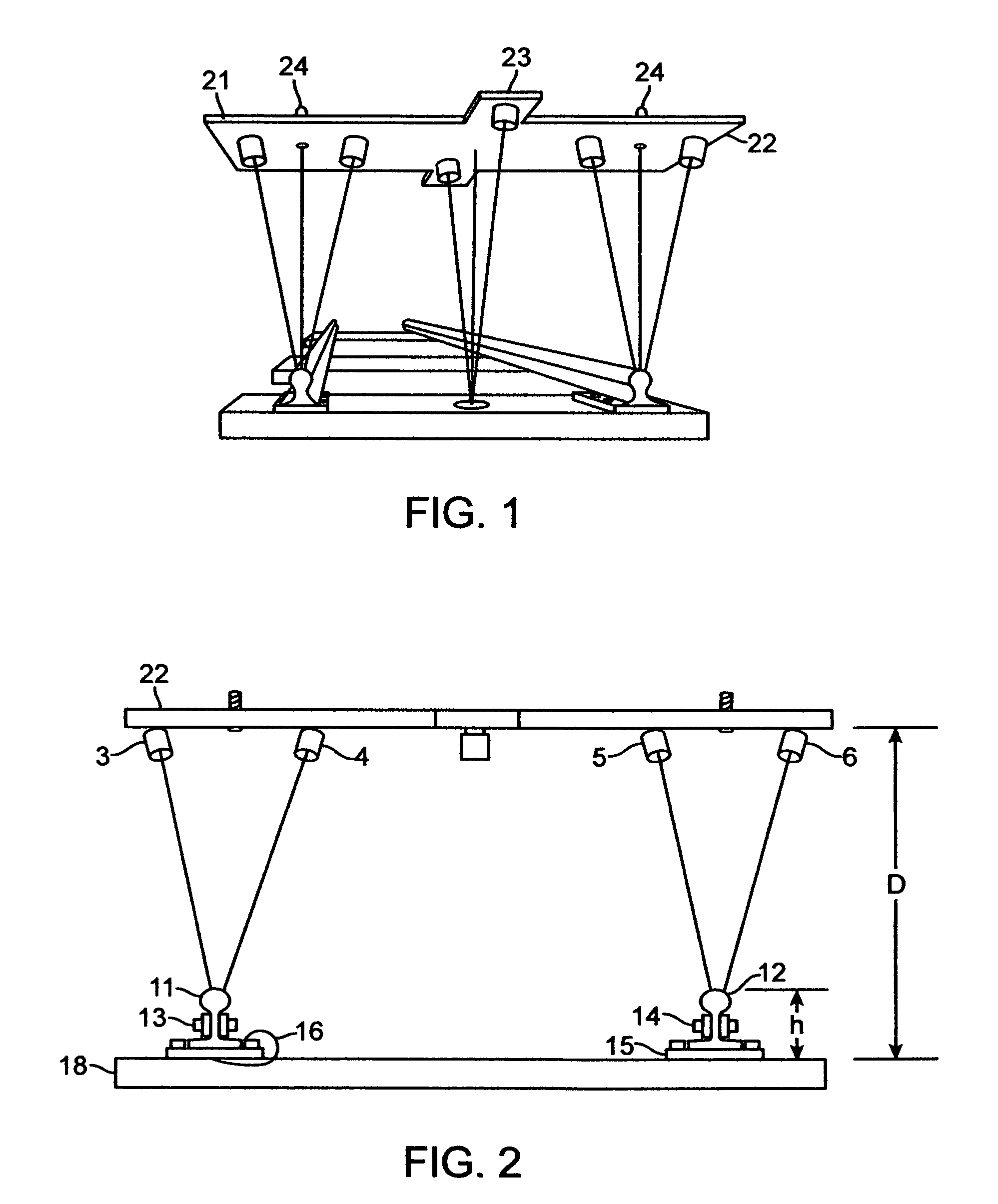
[0027]FIG. 2 shows the arrangement of the transverse cameras on structural member 22. The distance (D) of structural member 22 above...


PUM

PropertyMeasurementUnit
lengthaaaaaaaaaa
distanceaaaaaaaaaa
depthaaaaaaaaaa

Abstract

To emulate the 3D visual acuity of an individual track-walker, matched pairs of cameras (which simulate our human eyes) are mounted on a moving vehicle above the tracks. The cameras are mounted both transversely and longitudinally, to create 3D images in two orthogonal orientations, which helps to eliminate visual voids. The location and orientation of each pair of cameras is determined by its specific task, in the present case: (i) to examine each left or right rail for anomalies (two pairs), and (ii) to examine every tie for damage (at least one pair). The camera pairs enable measurements such as defect depth and track width variations. The images are compressed in real time for local storage or high-speed transmission for remote display. The basic arrangement of cameras can be amplified or modified as necessary to circumstances.

Description

BACKGROUND OF THE INVENTION[0001]1. Field of the Invention[0002]This invention relates to the in-depth inspection of objects which may hitherto have been examined as flat. The addition of an extra dimension replicates the human eye and contributes to a sense of depth, and adding valuable information for the inspection of diverse objects, in this case railroad ties and track. These objects can be instantaneously compared and sorted against three-dimensional (3D) templates which may reflect the ideal for that particular object. With advanced object recognition software inspection can be done at high speed and with great accuracy. The images can also be compressed in real time for high-speed transmission for remote display or analysis, or sent for compact storage. This invention is here applicable in the visible, infra-red, microwave and ultra-violet portions of the spectrum. It may apply also to sonar or ultrasound.[0003]2. Description of the Related Art[0004]Because rail inspection h...

Claims


Application Information

Patent Timeline
Patent Type & Authority Patents(United States)
IPC IPC(8): H04N13/02B61K9/10G06K9/00H04N7/18G01N21/17G06T7/00H04N13/239B61L23/04
CPCH04N13/0239B61K9/10G06T7/0004G06T7/0077H04N13/0242B61L23/042B61L23/045G01N2021/1785G01N2291/2623B61L23/044G06T7/001G06T2207/10021G06T2207/30108G01N21/9515G01N2021/8887G01N2021/9518H04N13/239B61L27/53H04N13/243
Inventor PRINCE, JOHN H.
Owner PRINCE JOHN H
Why Eureka
Try Eureka