Wall of turbo machine and turbo machine

a turbo machine and wall technology, applied in machines/engines, stators, liquid fuel engines, etc., can solve problems such as flow turbulence, and achieve the effect of reducing the loss caused by flow through the gap of axially adjacent walls

Active Publication Date: 2015-06-09
IHI CORP +1
View PDF29 Cites 3 Cited by
  • Summary
  • Abstract
  • Description
  • Claims
  • Application Information

AI Technical Summary

Benefits of technology

[0012]According to the present invention, loss due to turbulence of flow through the gap of axially adjacent walls can be reduced.

Problems solved by technology

The presence of the gap tends to cause a turbulence of the flow close to the wall surface.

Method used


Image

  • Wall of turbo machine and turbo machine
  • Wall of turbo machine and turbo machine
  • Wall of turbo machine and turbo machine

Examples


Embodiment Construction

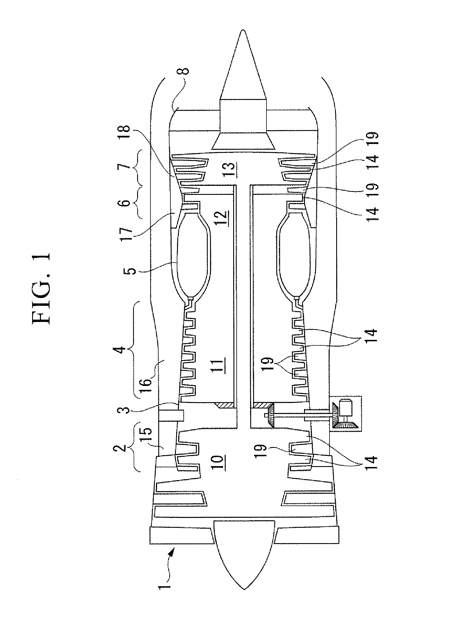
[0026]FIG. 1 is a schematic cross-sectional view showing a gas turbine engine (turbo fan engine) used in an aircraft or the like. The gas turbine engine includes; an air inlet 1, a fan low pressure compressor 2, a fan air outlet duct 3, a high pressure compressor 4, a combustion chamber 5, a high pressure turbine 6, a low pressure turbine 7, an exhaust duct 8 or the like.

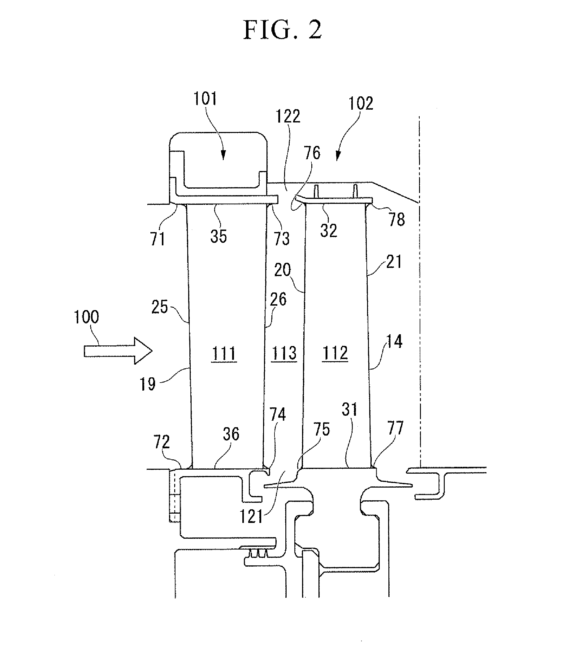
[0027]The fan low pressure compressor 2, the high pressure compressor 4, the high pressure turbine 6, and the low pressure turbine 7, each include a rotor with a plurality of blades (rotor blades) 14 on the outer periphery of rotators 10, 11, 12, and 13 serving as bases, arranged spaced apart from each other in the circumferential direction, and a nozzle in which a plurality of blades (stator blades) 19 are arranged space apart from each other in the circumferential direction on an inner periphery of annular casings 15, 16, 17, and 18 serving as bases.

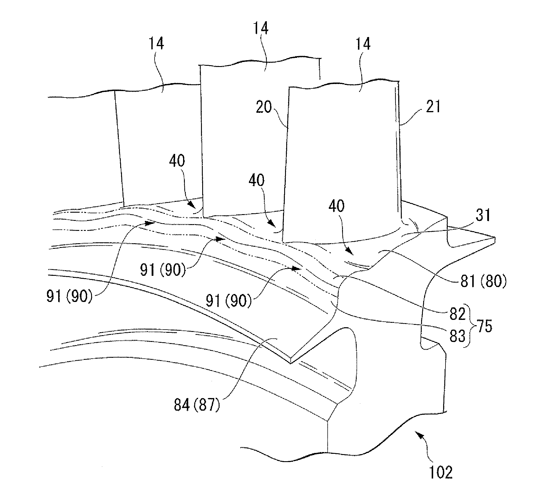
[0028]The plurality of blades 14 extend outward from the rotators...


PUM


Abstract

The invention relates to wall of a turbo machine having a cascade of blades. The wall includes: a first platform facing a first passage between blades in the cascade of blades; and a second platform facing a second passage between adjacent cascade of blades on an upstream side and cascade of blades on a downstream side, and having a circumferential outline having a distribution of radial positions. According to the invention, loss due to disturbance of flow through the gap of axially adjacent walls can be reduced.

Description

CROSS REFERENCE TO RELATED APPLICATIONS[0001]The present application is a 35 U.S.C. §371 National Phase conversion of PCT / JP2008 / 056181, filed Mar. 28, 2008, which claims benefit of Japanese Application No. 2007-087337, filed Mar. 29, 2007, the disclosure of which is incorporated herein by reference. The PCT International Application was published in the Japanese language.TECHNICAL FIELD[0002]The present invention relates to wall of a turbo machine that faces a passage, and to a turbo machine.BACKGROUND ART[0003]In a turbo machine having a row of stator blades and a row of rotor blades, the passage between the blades is surrounded by a wall on the radial inside and a wall on the radial outside (referred to as platforms, bands, shrouds or the like). The working fluid flowing out from the passage between blades of one blade row flows into the passage between blades of the next adjacent blade row. A gap is provided between the wall pair of axially adjacent blade rows (for example, refe...

Claims


Application Information

Patent Timeline
Patent Type & Authority Patents(United States)
IPC IPC(8): F01D5/14F04D29/52F04D1/10F04D13/14F04D23/00F04D29/32
CPCF01D5/143F04D1/10F04D13/14F04D23/008Y02T50/673F05D2250/184F05D2250/611F05D2250/711F05D2240/11F05D2240/80Y02T50/60
Inventor MITSUHASHI, KATSUNORITAKAHASHI, AKIRAHAMAZAKI, HIROSHIYAMAWAKI, RURIKO
Owner IHI CORP
Why Eureka
Try Eureka