Scale-up of flow-focusing microfluidic devices

a microfluidic device and flow-focusing technology, applied in the field of flow-focusing type technology, can solve the problems of affecting the accuracy of flow-focusing devices, prone to failure, and unsuitable control of very small dispersed phase droplets, and achieve the effect of preventing the pressure change from affecting another device and avoiding pressure fluctuations

Active Publication Date: 2015-06-16
PRESIDENT & FELLOWS OF HARVARD COLLEGE
View PDF52 Cites 11 Cited by
  • Summary
  • Abstract
  • Description
  • Claims
  • Application Information

AI Technical Summary

Benefits of technology

[0052]A further advantage of the present invention is that each device within an array operates essentially independently from the other devices in the array. Thus, if a device clogs or otherwise degrades, the other devices in the array can continue to operate.
[0053]An array of devices connected as described herein using a fluid distribution article also undergoes a very short turn-on transient behavior, in contrast to single-layer fan-out schemes that suffer from long-lived oscillations before steady-state operation is reached. For example, the turn-on transient behavior in a device of the present invention may be less than about 10 minutes, less than about 5 minutes, less than about 1 minute, less than about 0.1 minutes, etc.
[0054]Pressure oscillation due to hydrodynamic coupling is a common problem in microfluidic devices, particularly when elastomeric materials, such as PDMS, are used in the fabrication of the devices. For example, fluid pumped into a channel in an elastomeric microfluidic device can cause expansion and contraction of the channel thereby introducing a pressure wave in the fluid. In embodiments where the channel serves a plurality of microfluidic devices, a pressure wave can introduce fluctuations in the pressure of the fluid feeding into each of the devices connected to the channel. In some embodiments, the present invention substantially avoids these pressure fluctuations by controlling the volume of the channels feeding the devices. In some cases, a pressure change in a device may be relieved by the fluid distribution channel thereby essentially preventing the pressure change from affecting another device. For example, a fluid distribution channel connected to a first and second device that are in fluid communication with each other can allow the first and second device to be decoupled from each other.
[0055]The following tests will be useful for allowing one skilled in the art to design an array of microfluidic devices substantially without hydrodynamic coupling. For a 1-D array of N essentially identical devices connected by a distribution channel, each device has a hydrodynamic resistance value Rd, and the distribution channel has a hydrodynamic resistance Rc1 over the distance between adjacent devices (i.e., the resistance per segment). It is understood that the resistance may be different, but within the same order of magnitude, between inlets and outlets of a device. For example, the resistance between the oil inlet and the device outlet may be different in comparison to the resistance between the water inlet and the device outlet. If Rc1 is much less than Rd, the fractional difference in flow rates between the first and last devices in the array is less than N*Rc1 / Rd. In some cases, this quantity is maintained below 50%, below 40%, below 30%, below 20%, below 10%, below 1%, below 0.5%, below 0.1%, etc.
[0056]For a 2-D array of M×N devices, arranged in an M×N grid with M rows of devices, each containing N devices and each row being served by its own set of first-generation linear distribution channels, the hydrodynamic resistance between the inlet of a first-generation distribution channel and the corresponding outlet is approximately Rd / N, assuming that Rc1 is much less than Rd. To deliver fluid equally to each of the M rows of devices, the second generation distribution channels should have resistance per segment Rc2 much less than Rd / N. In this case, the fractional difference in flow rates between the first and last rows of devices is less than M*N*Rc2 / Rd. To maintain essentially equal flow per device at the same precision as for the 1-D array, the second-generation channels should be designed to have Rc2<Rc1 / M.
[0057]Similarly, in a 3-D array of K×M×N devices, arranged in K planes of M×N grids, the third generation of channels should have resistance per segment Rc3<Rc2 / K.

Problems solved by technology

Formation of dispersions typically is carried out in equipment including moving parts (e.g., a blender or device similarly designed to break up material), which can be prone to failure and, in many cases, is not suitable for control of very small dispersed phase droplets.
Specifically, traditional industrial processes typically involve manufacturing equipment built to operate on size scales generally unsuitable for precise, small dispersion control.
However, polydispersity of the dispersed phase can in some cases be limited by the pore sizes of the membrane.
Batch production of discontinuous fluids are prone to difficulties in product uniformity.
These problems can be compounded for complex structures such as double emulsions (drops-in-drops) or triple emulsions (drops-in-drops-in-drops).
A further difficulty for double or triple emulsions is poor encapsulation efficiency, where substantial amounts of the innermost phase leak out into the outermost phases, which can limit the usefulness of such emulsions as carriers for valuable or volatile compounds such as drugs, flavors, or fragrances.
Such control comes at the cost of forming emulsion droplets essentially one at a time, each microfluidic device producing only small amounts of product on the order of fractions of a milliliter per hour.

Method used


Image

  • Scale-up of flow-focusing microfluidic devices
  • Scale-up of flow-focusing microfluidic devices
  • Scale-up of flow-focusing microfluidic devices

Examples


example 1

[0117]This example demonstrates the fabrication of a parallel drop formation system.

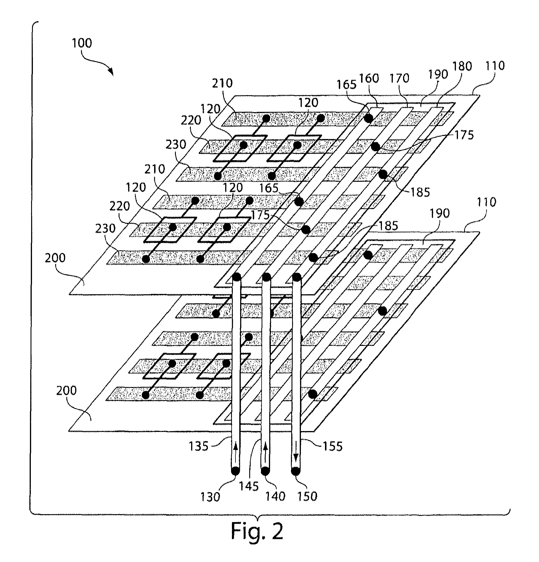
[0118]An array of microfluidic drop formation devices was fabricated from PDMS (polydimethylsiloxane) using standard multilayer soft lithography. The fluidic channels were arranged in a PDMS layer to have solid walls and ceilings but open floors. Fabrication of the channels was completed by bonding the channel-containing layer to a base of glass or PDMS. A channel in one layer can be connected to a channel in an adjacent layer by punching a hole in the ceiling of the lower layer channel.

[0119]In this example, the bottom-most layer contains an array of microfluidic devices, which are not connected together within this layer. This device layer was plasma bonded to a glass slide coated with a thin layer of cured PDMS elastomer.

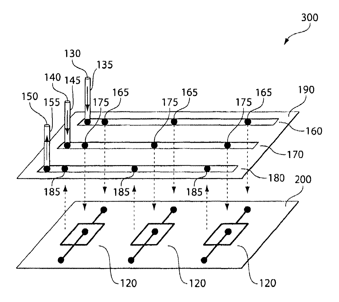
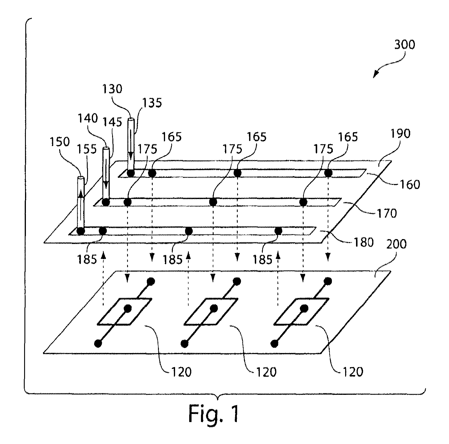
[0120]On top of the device layer was bonded a first distribution channel layer containing an array of fluidic channels, with spacing that matches that of the inlets in the device ...

example 2

[0124]This example demonstrates the calculation of channel dimensions for a parallel microfluidic device.

[0125]As a sample calculation, the desirable channel dimensions to serve a 5×5 array of T-junctions producing simple emulsion droplets was estimated using the following equation, which is known in the art:

R=[(12*μ*L) / (w*h3)]*{[1−[(192 / π5)*(h / w)]]−1},

where “R” is the resistance in a rectangular microchannel, “μ” is the fluid viscosity, “L” is the channel length, “w” is the channel width, and “h” is the channel height. T-junctions with channel length 4000 μm, width 50 μm, and height 25 μm, have resistance of about 100 kPa*s / μL assuming a viscosity of μ=1 mPa*s. If the first-generation distribution channels have height 150 μm, width 1500 μm, and the distance between adjacent devices is 10,000 μm, then the resistance per segment is Rc1=0.2 kPa*s / μL. This affords equal flow division between the 5 devices at the 1% accuracy level. For the second-generation distribution channels, increa...

example 3

[0126]This example demonstrates parallelization of double emulsion formation.

[0127]Each dropmaking unit included two sequential cross junctions as shown in FIG. 12. An array of units was molded in one monolithic block of PDMS using standard soft lithography. Inlet and outlet holes were hand-punched, and plasma bonding was used to seal the microchannels to a glass base plate. Plasma bonding was again used to seal a layer of distribution channels onto the array. To make the channel surfaces in the devices hydrophobic for drop formation, the assembled device was flushed with Aquapel (a commercial auto glass treatment) and purged with air. The device was baked for several hours to dry the remaining Aquapel.

[0128]To produce double emulsions, the following fluids were injected through the distribution channels: 1-octanol as the innermost phase, water with 0.5% (by weight) sodium dodecyl sulfate (“SDS”, a surfactant) as the shell phase, and HFE-7500 oil with 1.8% (by weight) “R22” surfacta...


PUM

PropertyMeasurementUnit
diameteraaaaaaaaaa
total flow rateaaaaaaaaaa

Abstract

Parallel uses of microfluidic methods and devices for focusing and / or forming discontinuous sections of similar or dissimilar size in a fluid are described. In some aspects, the present invention relates generally to flow-focusing-type technology, and also to microfluidics, and more particularly parallel use of microfluidic systems arranged to control a dispersed phase within a dispersant, and the size, and size distribution, of a dispersed phase in a multi-phase fluid system, and systems for delivery of fluid components to multiple such devices.

Description

RELATED APPLICATIONS[0001]This application is a U.S. National Stage filing under 35 U.S.C. §371 of International Application No. PCT / US2010 / 000753, filed Mar. 12, 2010, entitled “Scale-up of Microfluidic Devices,” by Romanowsky et al., which claims the benefit of U.S. Provisional Patent Application Ser. No. 61 / 160,184, filed Mar. 13, 2009, entitled “Scale-up of Microfluidic Devices,” by Romanowsky, et al., and of U.S. Provisional Patent Application Ser. No. 61 / 223,627, filed Jul. 7, 2009, entitled “Scale-up of Microfluidic Devices,” by Romanowsky, et al., all of which are incorporated herein by reference in their entireties.FEDERALLY SPONSORED RESEARCH[0002]This invention was made with government support under Grant No. DMR-0213805 awarded by the National Science Foundation. The government has certain rights in the invention.FIELD OF THE INVENTION[0003]The present invention relates generally to flow-focusing-type technology, and also to microfluidics, and more particularly parallel ...

Claims


Application Information

Patent Timeline
Patent Type & Authority Patents(United States)
IPC IPC(8): G01N15/06G01N33/00G01N33/48B01J19/00B01F3/08B01F13/00B01L3/00B01F25/46
CPCB01J19/0093B01F3/0807B01F13/0062B01J2219/00015B01J2219/00783B01J2219/00828B01J2219/00831B01J2219/00833B01J2219/00837B01J2219/00889B01J2219/00891B01J2219/0097B01J2219/00975B01L3/502784Y10T137/8593Y10T137/0318B01F23/41B01F33/3011B01J13/04B01J19/00B01F23/4105B01F2101/23B01L2200/0636B01L2200/0673B01L2300/0816B01L2300/0861
Inventor ROMANOWSKY, MARKABATE, ADAM R.WEITZ, DAVID A.
Owner PRESIDENT & FELLOWS OF HARVARD COLLEGE
Why Eureka
Try Eureka